Build Your Own Tube Tester
In my workshop a tube tester was needed. Used tube tester are quite expensive. So I decided to build a tube tester by myself with old parts, which are easy to implement. For random testing and measuring my tube tester sufficient.
The principle: The concept is very flexible. Enhancements are possible. The tube tester consists of two adjustable stabilized voltage sources with adjustable current limit to the anode voltage and screen voltage, and a negative voltage source of 0 to 30 volts for the grid voltage. In addition, 6.3 volts and 4 volts ac for the filament will be generated. Other filament voltages are provided by an external stabilized laboratory power supply.
Previously was a tube tester duty in any radio workshop. Tubes were in the past very expensive and could not be easily replaced on suspicion. Today we can build very accurate tube tester with relatively little effort itself thanks to digital multimeters and modern voltage stabilized power sources. I myself was amazed at how many tubes which I had gained in my youth from old TVs, seems to be defective. From three EF183 example was a completely useless because they did not show any anode current.
This project is a continuation of my power supply 1-250 volts DC . The anode voltage and the filament voltage were in this way already realized.
Measurement process of the static tube test: The voltages (filament voltage anode voltage, screen voltage, control grid voltage) according to a table (see in the text below) is set and the anode current is read. Is this anode current is much too low, the tube is to be classified as having been consumed. The currents and voltages are with multiple instruments, which are very inexpensive now, read. The tube sockets are housed in a separate enclosure. The wiring is done with banana plugs and banana plugs.
Vacuum test: This made by switching on a 1 Meg ohm resistor in the control grid line. Vacuum tubes with por vacuum have a grid current, which generates a voltage drop across this resistor. The voltage of the control grid becomes less negative and the anode current increases. Some vacuum tubes with bad vacuum glow in operation inside blue before they are finally out of order.
Short-circuit test of electrodes: Most tube tester make the static measurement before a short-circuit test. Do we have a ohm meter with buzzer that sounds at short circuit, which is very fast. We connect one electrode of the ohm meter to pin 1 of the sockets and connect the other electrode gradually to pin 2, pin 3 and so on. Then we put one electrode on pin 2 and the other to pin 3, pin 4, pin 5 and so on. Now comes in the one electrode pin 4 and so on. So we can check all possible combinations quickly and without thinking for possible shorts.
Tube data book for the static test tube: the anode current at the specified electrode voltages must be known for the test. You can, for example, the tube data book (PDF, 20 MB) ofAVO be removed. I have a print out only part of the pages for all the tubes in the E, U, and P series. From when a tube is exhausted, can not be said in general. Is only 60% of the predetermined anode current is reached, the tube in most cases is too bad. The Röhrensockelbeschaltung, for example, under http://tdsl.duncanamps.com/tubesearch.php orhttp://ds.agavaceae.ru to learn. For the main tubes I have the tube data into a form entered, from which the necessary wiring the banana plug can be read directly. Underhttp://frank.pocnet.net/index.html there are also Röhrendtatenblätter. Vieviel% of the given anode current, the tube still does, I write with permanent marker directly on the tube in order to know exactly what my old tubes still can.
Determine slope: Set when an NF-end tube as the control grid voltage so that 30 mA anode current flow. Now change the control grid voltage of 100 mV. Changes mean that the Anodentrom to 0.5 mA, the tube at this operating has a slope of 0.5 mA / 100 mV = 5 mA / Volt. With good multimeters can read the changes. From such multimeters you could only dream of in the tube era.
Tube sockets and tube socket: The tube has a base which plugs into the socket. The pin assignment of the socket or sockets is always considered from the point of view on the solder tails.
Warning: The kits are to be understood as incomplete suggestions. For the electrical safety of any rebuilder is responsible. The necessary safeguards are not shown in the diagram. The touch guard is not already running! The presented tube tester is thus still in the experimental stage. Of the voltages of sometimes prevail just over 400 volts.

A power supply unit provides the heating voltages, and the voltages for the anode, the screen grid and the control grid is available. A rotary switch, the voltages can be supplied to an external meter.

Stabilized voltage supply for the anode voltage, and the screen grid voltage. C is to be connected with each other. For the transistors bipoleren any Kleinleistungstransitoren came from the scrap box for use.
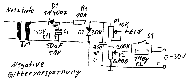
Grid power supply 0-30 volts. S1, the vacuum of the tube can be tested. A voltmeter should be connected to the wiper of P2. Fine adjustment of the voltage with P1. This allows the gate voltage change of 100 mV in order to determine the slope at a working point. This circuit is still experimental, because the cross-current of the voltage divider could be down to low.

Tube tester opened. Most of the parts are from the scrap box. For a further heating voltage is still space.

Left the screen voltage supply, the right grid power supply.

Test the screen grid power supply to a 25-watt light bulb.

Although the circuit is quite simple, the wiring was very time consuming.

The chassis for the tube sockets is made of painted wood, as it is easy to process.

The chassis with verchiedenen tube sockets and the corresponding banana sockets (8mm holes wood drill bit, high speed, low feed). For a pentode the chassis with six cables must be connected to the tube tester: 2 x heating voltage, cathode 1 x, 1 x control grid, screen grid 1 x, 1 x anode. May just adds a cable 7 for the braking grid, which is to be connected to the cathode.

Two versions are already wired. The other versions are gradually being wired.
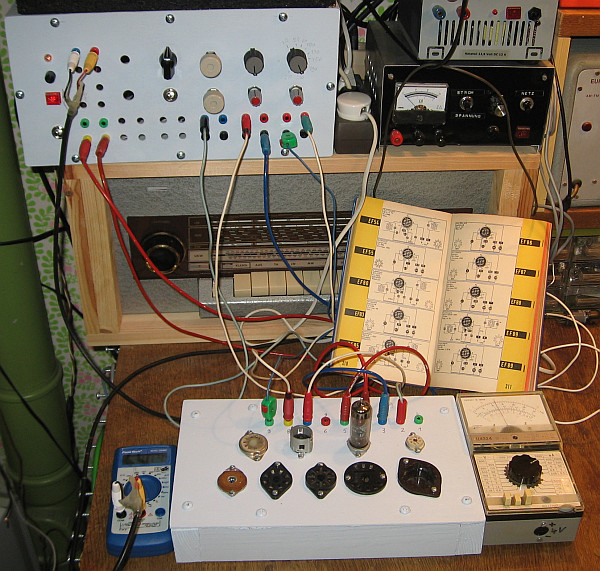
The tube tester in use. To the left, the tension meter for the anode, the control and screen grid can be read. This voltages are supplied via a switch on the tube tester multimeter. On the right of the moving coil anode current is read.

For the test, the anode current at the specified electrode voltages must be known. You can, for example, the tube data book (PDF, 20 MB) of AVO be removed. I have only printed part of the sides of the tubes of the E-series. From when a tube is exhausted, can not be said in general. Is only 60% of the anode current is reached, the tube in most cases is too bad. The Röhrensockelbeschaltung, for example, under http://tdsl.duncanamps.com/tubesearch.php to learn.

View from above.

From 12 old EF80 pentodes that once their service in the video IF amplifiers of old TVs did their service, four specimens were questionable bad.
Oscillation tendency to suppress: By wiring the tube can begin to swing, which distorts the results. This is most apparent in the hand sensitivity of individual cables. If these touches to their isolation, the anode current varies sometimes quite strong. Especially swinging joyfully are modern chip grid tubes with their high steepness.
Remedy is achieved by routing the control grid cable away from other cables. It is better to shield the control grid cables. In addition I have taken RG58 coaxial cable and earthed only at the voltage source. Additionally, I have a ferrite core attached directly to the control grid connection. In Novalsockeln Pin 2 is very often connected to the control grid.
In the plug-in cable for the control grid voltage I could have installed a resistor in place of the Toroidal Ferrite Core. But directly to the frame, that is, where it would be most effective, a resistor is not so, because not all of the tubes could then be analyzed. Imagine Just imagine a resistor in the anode lead. The measurement result would be distorted. This ferrite ring cores for EMC applications that I use, achieved with 7 turns 140 uH and already have at 1 MHz, a very poor finish of 15 to 20, which is desirable in this case. Because that corresponds to yes after the equivalent circuit of a series connection of an inductor and a resistor, which destroyed the HF. But in DC, this resistance does not exist, what is wanted for the static test again.
Eisenpuvlerringkerne, however, are unsuitable. They reach a too low inductance and are designed with their high quality factors for filter and oscillator circuits. I thought so, if you can replace this ring cores with steel nuts. Unfortunately, that will not work well, because the inductance was only a few uH.
It has no ferric drinking happy at hand, it can also carry out a series circuit of a capacitor and a resistor between the electrodes, for example, between the anode and the control grid.This would have built a frequency-dependent negative feedback or a Miller capacitance. The capacitors may, however, have no leakage currents, otherwise again the static test is falsified. Nor is it enough to turn on 1 nF capacitors between the electrodes.
Whether a tube vibrates, can be so easily festellen, since the anode current changes when you touch the cable to the control grid.

To suppress spurious oscillation, the control grid cable was designed as RG58 coax cable and the shield was connected on one side to the voltage source to ground.

Very effective ferrite ring cores are right on the control grid connection. In Novalsockeln he is usually at pin 2

Finally, I came up with the idea to install a ferrite core directly into the cable for the control grid voltage on the tube side. This ring cores can be cannibalized from old switching power supplies.
Be careful with the rotary switches for switching the voltage: via a rotary switch the anode voltage, the screen grid voltage and the grid voltage can be switched to a multimeter.This saves gauges and wiring. Some rotary switches, however, arises for a brief moment, a short circuit between the power sources during switching. This can destroy the power sources. In a worst case, the control gate voltage is set to 0 volts, and the other power source is short-circuited during the switching, resulting in the destruction of the potentiometer and a power MOS-FET with me! The rotary switches are to be checked out for this short-circuiting. These short circuits can occur even if the contacts at various levels can be selected.
Remedies and supplements: In order to achieve 250 volts anode voltage was also installed a 12 volt zener diode to increase the reference voltage. With a trim pot of 10 ohms the voltage adjusting knob the maximum voltage to exactly 250 volts can be set. This is handy, since many tubes are measured at 250 volts.
At the outputs of the two high voltage sources I have 1N4007 diodes connected to security in series with the voltage source, so that short circuits with faulty wiring can be avoided, if flow into streams in the opposite direction in the voltage sources.
In parallel with the rectifier diode of the grid voltage generation should for hum suppression nor a capacitor are switched by about 10 nF, if the tube tester should be used as a power supply for radio experiments.
A ferrite core in the lead for the grid voltage prevents very reliable Schwinneigung (see previous photo).
I made me a table of the main tube data from the wiring and settings are instantly recognizable. When it is complete, I will publish it.
The grid voltage generation is quite high impedance. The displayed voltage value true only if the meter is not removed by switching. My meter has an internal resistance of about 1 megohm.
For the anode current measurement I use additionally an even a digital multimeter. This makes it possible, when the grid voltage is changed slightly, determine the slope of the tube easier.
The plan is still a small shelf on which the power supply is provided. In the shelf which has two levels, the box can be provided with the tube sockets without having to remove the cable. Below is a compartment for the tube books and data sheets. Then everything is within reach.
An additional power supply is not installed for the heating voltages, which also includes a constant current source of 100 mA for the roar of the U-series.
The supply voltage for the anode receives a second IRF840 in parallel to distribute the power dissipation, so that power can be measured tubes.
If you measure the control grid voltage and the anode current with digital multimeters, can the slope at an operating point determine reasonably accurate to the control grid voltage is changed by 100 to 200 mV.
This Telefunken promotional film from the 1950s, which wants to encourage new replacement of spent tubes, maybe makes you want a tube tester.
Even more pictures:

Measurement of a PL36. The filament voltage comes from an external power supply.

A PL36 from an old line output stage is in operation.

A table of the main tubes accelerates the plugs of the cables and the adjustment of the voltages.

The wiring is completed for now. Harnesses were too risky because of possible oscillation tendency. Function before beauty. Colored wires and sockets prevent errors.

Space-saving stowed and ready for the next repair. The wiring is EF85 and EF89 prepared for the EF80.
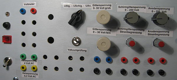
Finally the tube tester received a Beschritung. Space for further Heizspannungsquellen is still available. The connectors for the voltmeter, the control grid voltage, the screen grid voltage and the anode voltage can be tapped. The switching is done by a rotary switch. To the vacuum test, a 1-Meg-ohm resistor is switched into the grid supply. In a perfect vacuum, the anode current must not change.

With some color to the tube tester corner looks more uniform.
Old tubes and their use: The measured anode currents are documented with a felt pen directly on the tubes. The triode of 9 different ECH81 with an anode current of 5 mA tube according to Table gave the following values of the anode current in mA: 0.0; 2.7; 3.0; 3.7; 3.7; 3.8; 3.8; 4.3; 4,8. A copy was therefore defective in any case and delivered even after cleaning the contact pins no Anodentrom. The others I'll try and keep in a tube radio to get a feel for the performance of used tubes.
When a tube was not clear whether it was a PCL86 or PCL82. This could be found out with the tube tester.
When scanning of my tube stock from eye slaughtered radios and TVs I've found some clearly defective tubes and many very consumed. It was a real journey of discovery. Among them were also very good, which I will reserve as test tubes and specially marked. They should help you determine the whether it is worthwhile to replace a weak tube against a good one. A radio workshop could not proceed in this way and used to replace less used of course. Was a tube consumes loud tube tester, it is replaced by a brand new one if it improved the performance of the radio and the customer was willing to pay the new tube.
Meanwhile, I have a test basis of old and new tubes used as a test in a receiver. No difference between a ECH81 with over 90% and another with less than 50% anode current was observed. So stop tubes should not hastily discard.