Hum-free power supply for electronic circuits
Those, who make experiments with electronics and receiver circuits of long wave to short wave, needs a power supply, where the capacitors are connected in parallel to the rectifier diodes of the bridge rectifier, otherwise occurs hum.
Besides my little and noise free power supply project for 1 to 2 Amps output current depending on the voltage regulator used for reverse engineering. The power supply was designed for flexible use as possible. The Eagle files are located in the power supply-eagle.zip .
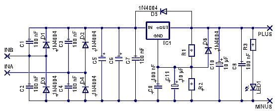
The dimensions of the individual values should be well known. See also auch http://www.elektronik-kompendium.de/sites/bau/0204301.htm und http://www.elektronik-kompendium.de/public/schaerer/ureg3pin.htm . Achtung: The 1N4004 diodes are suitable only for an output current of up to 1A.
Since you do not always have a fixed voltage regulator with the appropriate tension in his junk box, I have a voltage divider provided for this power supply, which you can optionally omit. R2 is then replaced by a jumper wire. D6, R1, C9 and C11 omitted. D5 is only necessary if the output of the fixed-voltage regulator supplies a voltage exceeding the same at the entrance could occur. The two filter capacitors C5 and C6 should after a rough rule of thumb together around 2000 uF per amp have output power. Whether a smaller value sufficient is try. R3, the series resistance of the LED, at 12 volts output voltage is about 1 kohm.
The capacitors C1 to C4 in parallel with the diodes D1 to D4 of the bridge rectifier are very important when the small power supply is to be operated at a receiver of long-to short-wave. Without these capacitors (100 nF) of the receiver appears verbrummt.
The layout of the component side seen:
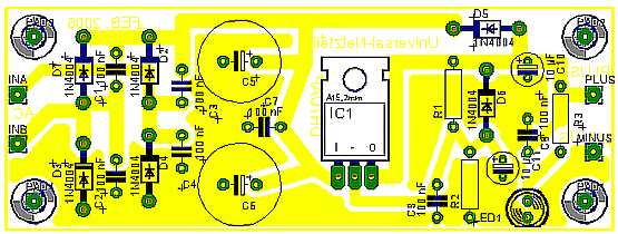
The layout of the circuit board of the Bestsückungsseite considered. It was created with Eagle. The Eagle files are located in the power supply-eagle.zip .
The board is printed on one side and has been Decoration is that you can mount the filter capacitors and axial types lying, if a low profile is desired.
Below a picture of the prototype:
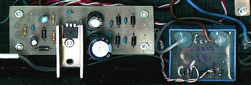
The ready made power supply in a FM receiver. The transformer was fixed with super glue and glued into the painted wooden casing. Before applying the adhesive, the side walls of the transformers were roughened.
The prototype runs with me for years in a self-built FM radio receiver . I always use depending on power loss a heat sink or a cooling fin for the voltage regulator. Why always buy a power supply? In a self-built at least you know that you can also do the work yourself.