How do I repair old tube radios?
The repair of tube radios is easier than many think. 90% of the errors are typical, age-related causes. However, tube radios are not for the absolute layman. It occurs in tube radios even after shutdown still dangerously high voltages that can kill a man! Before you approach ventures on a repair, in addition to the safety rules, the fundamentals of electrical engineering, tube technology and radio technology must be known. Only then is the practical advice and experience can be used properly and are valued sense. Really interesting form does the repair of old radio technology with the historical background knowledge.
Only with a basic knowledge of electrical engineering and broadcast engineering, a systematic troubleshooting capability. As is already described very much on the Internet, and it makes no sense to reinvent the wheel, I would like if possible to refer to existing links. Old tube radios can be customized with theoretical knowledge alone, however, repair is very time consuming. It is also important to know the typical errors and assess the age-related behavior of the part over 70 years old components.
The restoration is not the subject of this article. When restoring of Bakelite or wooden cabinets it comes to the most extensive restoration of the original visual appearance.
What are the typical defects of an old tube radios at a glance?
1. Mechanical problems and electrical contact problems: gummy and thus hard working mechanics of axes, pots, switches, and variable capacitors. Cracked or worn-scale hurry. Kontakschwierigkeiten by dirt and corrosion.
2. errors due to aging of components: Spent tubes, allowing the device is insensitive and distorted sounds. Spent tubes have a lower slope and a reduced anode current. Certain types of capacitors are prone to leakage currents, and thus alter the operating point of the tubes. Dried out electrolytics have lost capacity. Aged selenium rectifiers have an unusually high voltage drop in the forward direction. High ohmic resistors can be high impedance. More on "Typical defects of the components of old tube radios" .
Rarely are total failures of the components, but there are more changes to the component parameters before. Total failures are usually due to poor connections, which must be cleaned. Cold solder joints provide for loose contacts.
Why do we have so much fun wiht old tube radios? mechanical and electrical faults are almost never alone before. In some cases, the radio needs a new setup. When one adds to the restoration added to the designed repairing and restoring old tube radios for a fun hobby, which equally requires theoretical and craft knowledge. By the way, you learn a few words about the then technical development and past ideas of taste. Each tube radio embodies a piece of art and art history.
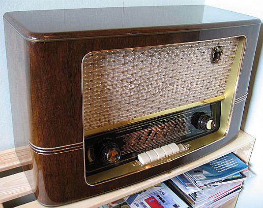
My favorite radio tube radio brown 555 FM built in 1955 from 1955 proves itself in daily use and delivers excellent sound quality on all broadcast bands. The tube set used was widely used for the following years: ECC85 (FM), ECH81 (mixer and oscillator), EF89 (ZF Regelpentode) EABC80 (NF-triode and diode for the demodulation of AM, FM and the control voltage generator), EL84 (audio amplifier) and EM80 (Magic Eye). The radio had the typical errors that can be removed easily ( more on that here ).
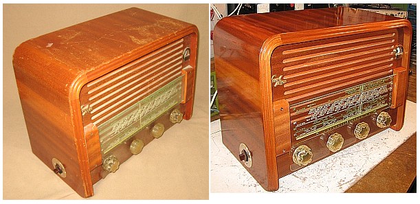
How to recover a fully functional piece of jewelry is made of an unsightly and defective radio, is under repair and restoration of an old tube radios chronologsich documented in detail in words and pictures. Time should be definitely one in the process.
Which tube radios do I start? Relatively easy to repair are tube radios from the late 40s to early 60s . Take radios without complex mechanism. Due to widespread tube sets, there are no major deviations circuit. This tube radios are available in large numbers and the procurement of spare parts presents no major problems. In order to appreciate old radios of the 50s, the help pages " The development of broadcasting technology in Germany after the 2nd World War "and" R / TV Service "with many interior views of old radios.
This video shows the mechanics of an old tube radios in action. Mechanical defects almost always have dirt, dust, sticky kitchen range and gummy oil as the cause.
What requirements do I need to bring? The Fundamentals of Electrical Engineering must be known. The following terms in their context must be familiar with: current, voltage, resistance, power, Ohm's law, parallel and series circuit, internal resistance, adaptation, coil, condenser, low pass, high pass, band pass, notch filter, band-stop, swing travel of all kinds, transformer, diode , bridge rectifier, electrolytic capacitor, variable capacitor, RMS and peak voltage, mixture of frequencies, mixture of AC voltages, negative feedback and positive feedback.
Books and Literature: Who the fundamental knowledge is lacking, for example, will help in the technical part of the books for preparation for the amateur radio examination. Tubes are allersdings no longer treated for amateur radio examination. Also recommended is the book "Radio of the 50s: restoration, repair and re-commissioning" by Eike reason.
Old Radio Craft books from the 50's are also very helpful. However, they lack in the description of the typical age-related errors that I " Typical defects of the components of old tube radios have compiled ". Under http://www.tubebooks.org there are plenty of free tube books as PDF scans, its us-American copyright has expired.
Schematics of old tube radios: These are available, for example on http://www.anova.at/ to download. There 6300 schematics are stored as JPG files in two zip files. The files are sorted according to the manufacturers. Members of Radiomusuem.org can access a large number of diagrams.
Basics of tube technology for Beginners: electron tubes are relatively easy to understand. Triode and pentode are similar to a field effect transistor voltage controlled amplifier devices that work similar to the JFET on Steurgitter with negative bias. Under http://www.elektronikinfo.de … roehren.htm there is already a practical introduction. Tubes age due to their operation. The electron-emitting ability of the cathode can in the course after the operating period. The effect is insidious. The gain can be claimed by it. The radio is insensitive. Tube tester can determine whether a tube is only fit. Also worth reading is the history of the electron tube , which provides an understanding of the different tube types. To get used to the tube circuitry, the employment is with a simple low-frequency power amplifier . Under " circuitry ", there are other clues. There the power supply circuits are explained.
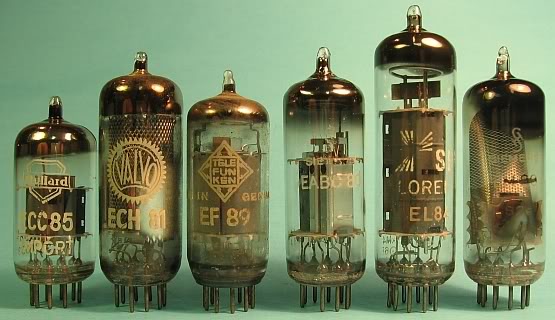
Tube set a radio from the 50s for nine-pin and Novalsockel for 6.3 volt filament voltage. From left to right: FM twin triode ECC85, mixing tube and Ozillatortriode ECH81, IF Regelpentode EF89, NF-triode and 3 diodes for AM and FM demodulation EABC80, NF-Endröhe EL84, EM80 Magic Eye ( full view here ).
The superheterodyne principle: Almost all "steam radio" 50s are as superheterodyne ( superhet receiver built). How the scheme works in a radio set that is under Superhet.htm http://www.jogis-roehrenbude.de … / and the following pages in detail. Only if this principle is understood reading the following repair advice makes sense. Anyone who even wants to build a medium-wave valve superheterodyne found here a detailed building instructions .
Superheterodyne balance: It is rare that a superheterodyne re-adjusted to be. Here at AM-balance this process is also described. When balance is between the filters for AM and FM IF to distinguish. The filters for AM and FM (VHF) are almost always given placed in the same shield cup, which may provide initial confusion.
Ratio detector Syndicate: If the FM signal is frequency modulated. The FM tuner provides an intermediate frequency of 10.7 MHz, which is amplified in the IF amplifier, and is then demodulated in the ratio detector. The following links provide information about Ableich the ratio detector:
– Balance of an FM IF amplifier with ratio detector
– Introduction to the FM demodulation
– FM FM calibration made easy

A ratio detector germanium diodes after the removal of the shield cup. Older Ratio detectors are constructed with tube diodes which are, for example, in the EAA91 or EABC80.
Are there during FM reception two maxima, the FM IF amplifier should be recalibrated. If the FM reception is distorted in transmitter center, the ratio detector mus be recalibrated. A ratio detector has a small electrolytic capacitor of about 5 uF and about 70 volts dielectric strength, bears the positive terminal to ground. This Elko has often lost its capacity and is therefore to be checked and replaced if necessary. Too small capacity leads to a faint sound with lack of bass. The capacity of the replacement is not critical and can be between 5 and about 33 uF. Important is the minimum required voltage strength.
Pin assignment of tubes: The page http://tdsl.duncanamps.com/tubesearch.php provides the data sheets and pinouts almost all common tubes.
Practical tips, safety rules and interesting links:
Safety: http://www.oldradioworld.de/safety.htm Who wants to survive, these rules must be observed! Allstromgeräte have, for example, no power transformer. The full mains voltage may be present directly on the chassis. The Röhrenbezeichungen such radios usually begin with U, such as UL84 or UCH81.
Wumpus compendium of tube radios: http://www.oldradioworld.de/hints.htm Very comprehensive and leaves nothing to question. I absolutely recommend working through the entire text of the three parts, so that one anrichet no damage by the installation and removal of the chassis.
Up to 1962 sin detailed repair reports of tube radios from about 1938 on: For more tips on restoration and repair old radios the side of the collection of my radios to find. There, click on the light blue headings to click on the repair and restoration reports. For examples, you learn very well.
Repair practice, collecting – why? Circuit Technology: Under http://home … nostalgia / reparatur.htm are worth reading pages which gives the beginner an overview.
Which capacitors are often broken? Certain capacitor types show age-related leakage currents that can lead to errors depending on the application in the circuit or may pose a safety risk. Under " Small Capacitor customer "or" problem capacitors "the problematic and unproblematic capacitor candidates are listed and illustrated. This should be seen. Mandatory one should replace the coupling capacitor to the grid of the NF-end tube, When this capacitor shows a leakage current, the anode current of the NF-tube is much too high, which can lead to more defects after themselves. Leakage currents can be determined by a series connection of a voltage source at 90 V, a safety resistor of about 1 Mega-ohms, and an ampere meter in the mA range. Some high-resistance ohmmeter are also suitable for the detection of leakage currents.
What are the components of old radios and what defects may have them? I have in word and image among these questions Typical defects of the components of old tube radios answered.
Capacitors form: When old electrolytic capacitors in the power supply not spent years in operation, they have high leakage currents and low capacity. You must turn on the radio before formed are. The electrolytic capacitors in the power supply must be checked if they do not get hot during operation due to leakage currents. Such capacitors may explode.
How to turn on an old and unknown radio for the first time? For safety, a bulb of about 60 watts should be installed. It lights up bright, the radio has a short circuit. What everything is still observed, for example, is here .
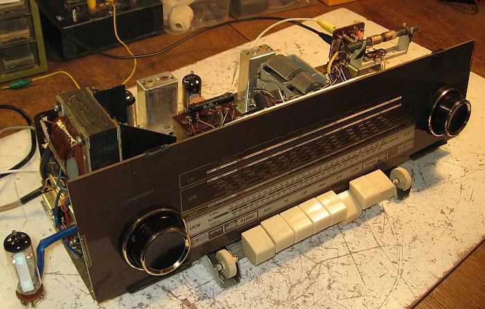
Chassis of a tube radios (Grundig 2460) from the front. The fragile glass scales should be treated with caution. His printed inside must not be cleaned, otherwise the print is blurred.
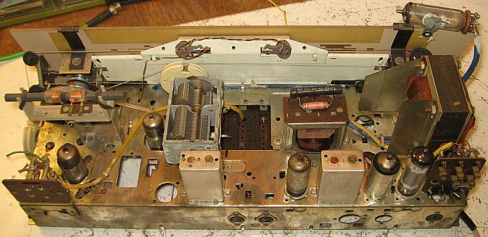
Chassis of an old tube radios (Grundig 2460) from above. The tubes from left to right: ECC85, ECH81, EF89, EABC80, EL84.
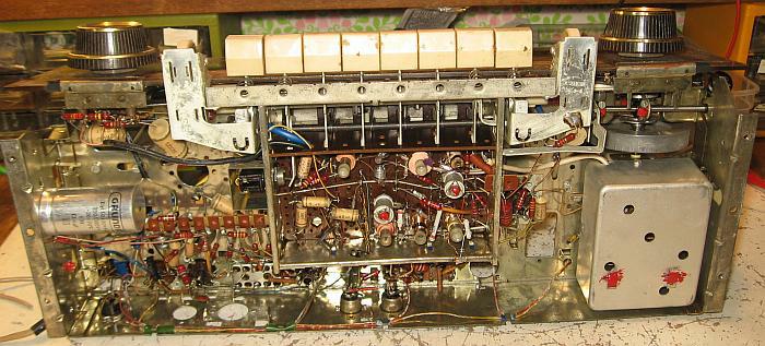
The same driver from the bottom shows the free wiring of the components. In the box at the bottom right there is the FM tuner.
How do you clean a chassis? There are people who clean the chassis in the dishwasher. This can go well. However, it can cause considerable damage. I do not advise urgently. It is better with soft brushes to remove dust without tearing the thin wires. Then, with many cotton swabs, toothbrushes and a mild detergent (or glass cleaner) to clean the metal surfaces. The tubes can be cleaned with glass cleaner, cotton swabs, toothbrushes and household paper towels, which must be taken to ensure that the printing will not be wiped away. With a purified chassis disappear unpleasant odors and Troubleshooting is enjoyable. Thickness of dust and grease layers also pose a fire hazard and the back of the dial printed glasses not scans are best at, otherwise the printing will be wiped out.
Parts Procurement: A compilation of procurement sources for tubes, parts, cleaners and accessories I have for example under " Sponsors of Radio Museum Bocket found ". In addition, you will find components on amateur radio flea markets or from friends and acquaintances who share the same hobby with a.
Idea of a small, cozy Radio Museum in Bocket , which specializes in tube radios of the brand Loewe. 300 exhibits have now been accumulated, which are also restored and repaired.
Video in English about the typical, systematic approach to the repair of an old tube radios.
Why work tube radios with such high plate voltages? Many know radio circuits for the reproduction and experimentation purposes, which operate with less hazardous for humans anode voltages from 6 to 60 volts. In tube radios but anode voltages are used by more than 200 volts. Why? The higher anode voltage is, the higher is also the load resistance of the anode to be dimensioned. The higher the load resistance is, the higher is the voltage gain. To obtain the volume for the operation of the loudspeaker, I also need high anode voltages to achieve the necessary performance. Gladly we would have used higher voltages, but then you need higher voltage capacitors strength. The lattice spacings of the tube must be kept larger to avoid flashover. Large lattice spacings go back on the cost of the pipe slope and therefore lower the voltage gain. The anode voltage of 200 volts is a compromise between many technical factors.
Portable radios, the battery tubes have to work with an anode battery , which provides 70 to 90 volts because of these tensions, the number of battery cells is still affordable. For radios, there are low-voltage tubes with 6 volts anode voltage, because at that time the electrical system yielded 6 volts. This low-voltage tubes for car radios were developed because at the time there was no suitable transistors for high frequency. The NF stage this car radio was built with transistors. The EF98 is such a low-voltage tube, which is often used in modern times for experiments with Rückopplungsempfängern.

Various types of resistors from old TVs and tube radios of the 40s to the 70s. Resistors with color rings after the resistor color code are marked came on later. Especially the high-impedance resistors tend to age to still be high impedance, since their carbon layer is particularly thin and long. Sometimes you can find the coiled carbon layer under the paint layer.
My personal approach to the Troubleshooting and Repair: It is assumed that the heating elements glow, the anode voltage is present, the Gleichrichterelko is not warm and otherwise also no suspicious smells coming (pungent odor = Interturn a transformer or a choke, rotten eggs = selenium rectifier) . Suppose also had no reception or poor reception. An unknown radio was also set by the usual precautions in operation. I assume that the practical fundamentals of electrical engineering and radio engineering are known. The following sequence has been proven to me:
1 of my choice clean all contacts through targeted and economical spraying with RF contact spray (tuner spray, eg Kontakt Chemie tuner 600 or contact 60). Additional contact faults make it hard to troubleshoot. Bad tube contacts are a common cause of error. Likewise, based crashing pot on dirt which can be removed with contact spray. Almost all old radios suffer from corroded or dirty contacts. According to the data sheet of the chemical contact , the contact cleaning consists of three phases. Contact 60 dissolves corrosion and dirt, contact WL flushes dirt and corrosion residues away, contact 61 protects the contacts clean.
2 with suitable odorless penetrating oil ("rust remover" for example, CRC 5-56) of my choice to make the mechanics continuously without oil the scales hurry. Always only selectively and sparingly spray. Errors in mechanics are almost always based on gumming the moving parts. Patience is worth to leave for the penetrating oil a few hours.
Third review of all electrolytic capacitors, of whom there are in a tube radio not so many out there, and optionally install a replacement. Precaution intact capacitors connected in parallel, as the old capacitors have capacitance loss. Of course, match the polarity and dielectric strength.
4 coupling capacitors to the grids of the NF-tubes are mandatory replaced because their leakage currents almost always significantly adjust the operating point. The excessive anode current makes for a distorted sound, premature wear of the output tube and overloading of the mains transformer to high ripple on the anode voltage.
5 When the radio is dead, I dine with a simple multivibrator from back to front the signal following a signal to the grid on in order to limit the errors.
6 If it is not booming despite supplied signal at the grid of the output tube from the speaker or beeps measure AC voltages at the speaker or audio output transformer.
Verify 7 DC voltages on the electrodes of the tubes. For this I took some notes as a rough guide the DC voltages of a radio with the same set of tubes. Typical DC voltage values are shown as the diagram of the Braun 555 FM . These voltage values can also be used as a guide for tube radios with the same or a similar set of tubes. Deviations of plus or minus 10% usually have no meaning. An example: The voltage drop across the cathode resistor of the EL84 is at most circuits 6-9 volts. By the given set of tubes and the economic constraints the former developer did not have much leeway. The voltage on the screen grid is of course always smaller than at the anode.
Check 8 AC voltages at the anodes with the oscilloscope. In addition I have re-written rough comparison values to a radio with the same or a similar set of tubes. Such documents are worthwhile.
9 Screening for obviously defective solder joints and re-measurement of the affected stage resistors. In the off and de-energized state (discharged filter capacitors!) Can be re-measure almost all opposition without expansion with an ohmmeter. If a short circuit is measured, switch to a different wavelength range and measure again. If resistance is suspected, unsolder one side and measure. Most of the high-impedance resistors are still high impedance. Congested resistors have distinct color changes. The cause is usually a defective capacitor in the vicinity. Rarely, it is a tube with electrodes conclusion.
10 replacement of the well-known because of their leakage currents capacitors problem-types (paper, ERO100, Tropydur etc) of the affected level.
Replace 11 If still poor reception, the mixing tube (ECH81 etc). This is often consumed. It is convenient to have a set of tubes from which we know that it is okay to exclude tube errors. For starters, one ECC85, for testing purposes ECH81 and EL84 enough.
12 When you have poor FM reception, the ECC85 is often consumed. The defective Elko on the ratio detector also ensures quiet reception. It is the one capacitor, the positive terminal is connected to ground.
13 If one wants to know whether the oscillator FM tuner swings, I work with a self-built Diodentastkopf and a multimeter. The probe I think just a cm from the voice coil. This also goes for the other wavebands.
Diodentastkopf for the detection of high frequency to the FM band.
14 If the sound is still not satisfactory always, because it sounds too dull or too bright, you can replace the capacitors in the tone control.
15 If the error occurs periodically and in a minute and auschaltet, is usually a tube to blame, it is often the ECC85 or EC92 in the FM part. These tubes are also usually responsible for a drifting of the FM station. Used tubes, which are recognized by the tube tester as well, can also drift away.
16 loose contacts can be found by gently tapping with an old ballpoint pen to the suspect components. Rivetings can provide for bad ground contacts, which can lead to mysterious errors with poor reception services. Tubes can use a chipper to be tapped or similar isoliertern object to track internal loose connections and internal short-circuits the tubes.
17 If long-wave or medium wave not go, but everything else works, the input coils for long and medium wave may have been destroyed by lightning.
I think with these tips you can get 80 to 90% of the errors in the handle. The remaining 10 to 20% can of course be difficult, especially if several errors occur simultaneously. If you do not progresses, specializing in old tube radios forums can such as the Wumpus-Gollum-Forum , which is led by an experienced professional with decades of professional experience in this field help. More tips can be found at " The repair helper of Magic Eye ".
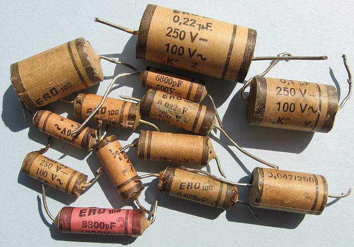
Apart from the famous Wima Tropydur (cough drops) as shown below paper capacitors ERO also are 100 due to high leakage currents often defective. Defective capacitors must not be replaced all mandatory in old tube radios. It also depends on what function they fulfill in the circuit.
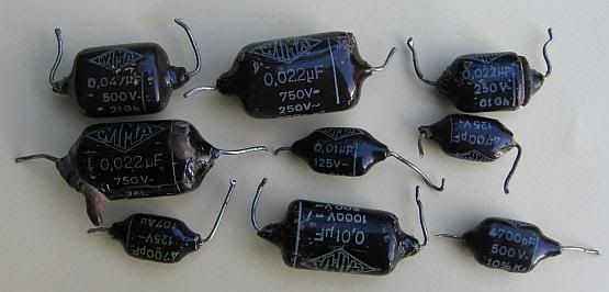
The WIMA Tropydur capacitors, which were also called cough drops have, almost without exception, leakage currents and employed generations of radio and television technicians for their exchange against other types. Tropydur capacitors, paper capacitors and other capacitors can be replaced by modern plastic film capacitors corresponding dielectric strength.
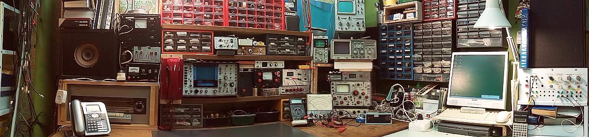
The following measuring devices I use: Simple test transmitter, multivibrator multimeter to 1000 volts DC and built-in capacity meter and ohm meter, Used oscilloscope to 20 MHz. Selfmade digital L / C meter for checking coils, a tube tester as a DIY project is not yet completed.
A few examples of typical errors in any order:
1 An amplifier stage built with a pentode shows no gain. The measurement shows that the screen grid is no voltage. Two causes are likely. Either the blocking capacitor from the screen grid to ground a short circuit or resistor for the screen grid is interrupted. In an idle state, we measure the resistance with an ohmmeter. If the resistor is ok, there is probably a short circuit of the capacitor.
2 The anode plate of the NF-end tube is dark red glowing and / or the sound is distorted. The voltage drop across the cathode resistance is much too high and indicates a high anode current. We clamp the coupling capacitor from the control grid and find that now drops less voltage at the cathode resistance. It is thus clear that the coupling capacitor has a leakage current, which provides a positive control grid voltage, so that the anode takes too much power.
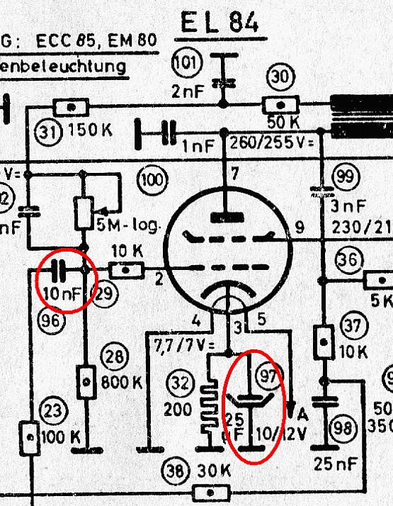
The classic, age-related errors almost all tube radios. If 10 nF capacitor, which represents the coupling capacitor to the control grid of the EL84 (NF-end tube), a leakage current, has the anode current of the EL84 increases dramatically, which leads to distortion and increased wear. Due to the high anode current and the voltage between the cathode and ground is higher than indicated. Has lost at the cathode terminal of capacity of Elko, this has an effect on a poor bass response and volume is low. Had the 1nF capacitor to the anode of the EL84 a leakage current, this would still be so small compared to the anode current, that will not affect the function of the circuit would determine.
3 The FM broadcast sound too quiet, somewhat distorted and to hel l Often this is due to the electrolytic capacitor in the ratio detector. Its positive pole is connected to ground. He probably has lost capacity.
4 The radio will not turn on and does not get mains voltage. This may be due to the toggle switch, with the mains voltage is switched on. With penetrating oil (rust remover) and some voltage-free switching operations can be made to work again without having to be removed. After spraying, you should wait a few days until all the flammable vapors have evaporated, otherwise the switch may explode due to Einschaltfunken.
5 The radio hums very strong. Often the filter capacitors of the power supply have dried up and have lost capacity. If these capacitors, which are located together in a metal cup, not warm, modern electrolytic capacitors from 50 to 100 uF can be connected in parallel with the required dielectric strength. It is important to ensure the correct polarity, otherwise explode the capacitors with a loud bang. However, the ripple can also be due to a defective tube, when a fine circuit between the indirectly heated cathode and the filament is present.
6 The FM reception is very insensitive. An exchange of the ECC85 and / or ECH81 may be the solution. The anode resistance of the Heptodensystems ECH81 may be too high. If no good as new ECC85 is available, there is nothing a transistorized VHF preamp use. Instead of the ECC85 can also in most cases the very steep tension mesh tube PCC88 use, resulting in an increase in sensitivity. It should be ensured that no resistors are overloaded because the PCC88 requires a higher anode current than the ECC85. Moreover, in the PCC88 missing a shield between the two Triodensystemen, whereby the RF of the oscillator can be emitted via the Anntenne, which could result in interference to other FM receivers.
7 The variable capacitor (variable capacitor) can be difficult to move or is seated. The axle bearings with a few drops of rust remover provided and leave. No oil can get to the scales hurry. In persistent cases, expand the variable capacitor and at 50 ° C heat in the oven, so that solves the resin. Alternatively, the variable capacitor can be heated with a hair dryer and then in a 40 ° to 50 ° C warm suds (detergent for the washing machine) to be cleaned. Then rinse well with water and dry. It used to be the variable capacitors boiled for 10 minutes in a pot on a stove in water and washing powder. However, this can destroy the plastic parts with newer variable capacitors or can form bubbles the paint in older variable capacitors. Therefore, this method should be used only as a last resort, but almost always leads to success. Fixed axes can also be heated with a thick soldering iron of 100 watts until the resin oozes out. Before, to remove near-mounted plastic parts. With variable capacitors with reduction gears no violence must be used, otherwise the gears are damaged.
8 The FM reception mode is launched periodically on and off or drifts away. Then there is usually also on the ECC85, UCC85 or EC92 in FM tuner.
9 The magic eye not or only very weakly illuminated. This is a very common mistake. During the service period, the luminosity of the green florescent layer of the display tubes decreases. If you look closely at the luminous layer, sometimes it can be seen, with what signal strength the preferred stations are received over the years. An increase in the operating voltage can remedy the situation in the medium term. The high voltage, however, can result in burning the Pertinaxsockel of magic eye. In the long run helps just a new magic eye. Unfortunately, such tubes have become expensive since they are no longer manufactured. However, the error has no influence on the rest of the functionality of the receiver.
10 Torn scales haste can be described by a colorless nylon cord (approx. 0.4 mm diameter), which are available in clothing stores, replace good, if can not be "right" scale hurry obtain.
11 No reception or poor reception on medium wave. Assume that the FM reception works. Most of then are dirty contacts the cause. Clean the contacts of the key set with tuner 600 or coarse dirt with contact 60 and move it. Medium wave reception works equally under the laws of wave propagation only after sunset and in good days in the summer are to receive only local final (Video sample " medium wave reception at noon "here). If the recipient does not have a ferrite antenna, at least a couple of feet of wire must be attached as an antenna. Unfortunately receives an indoor antenna also many homemade interference from TV, fluorescent lights, switching power supplies, etc. have proved for medium wave reception loop antennas. An outside antenna of a wire is often even better and may extend over several 10 meters long. This can be received in the winter nights with a tube radio 50 to 70 medium-wave transmitter. Eighth Outdoor antennas in lightning protection and disconnect the antenna when not in use. In addition, helps to ground the unit to the ground socket with the central heating. Above all, should the affected coupling capacitors be replaced with capacitors with VDE certificate before connecting an antenna or earth at Allstromgeräten. Under no circumstances the chassis of a Allstromgerätes may be directly connected to the protective conductor or the central heating radiator, because depending on the location of the power plug in a short circuit.
12 Irritating odor for a few minutes after turning on the radio. Situation is usually a short-circuit (winding short) within the supply transformer. Thus, the transformer is hot and the voltages across the windings are absent or lower than indicated. There is risk of fire. A functioning transformer is only lukewarm or no more than about 40 ° to 50 ° C hot. The defective power transformer must be eye exchanged for a matching type, or it must be re-wound, which requires experience and patience.
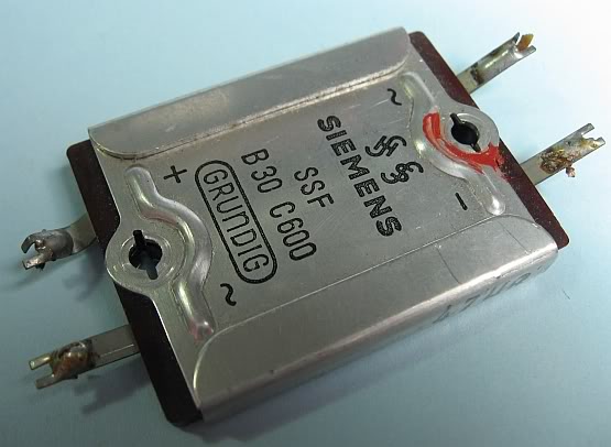
Selenium bridge rectifier in flat package. This one would not even be suitable for a power supply of tube radios, because according to the type designation, the allowable voltage is only 30 volts at a maximum output current of 600 mA is (B 30 C 600).
13 It smells like rotten eggs. This is due to a defect of the selenium rectifier in the power supply . Since selenium rectifier normally have a voltage drop of about 20 volts per rectifier route, this can not be replaced easily by silicon diodes such as the 1N4007. It is to use a matching series resistor, which destroyed the excess voltage and limits the inrush current. In addition, capacitors are in parallel to the silicon diodes to avoid hum on long-to short-wave. Learn more about this under "selenium rectifier replaced with modern silicon diodes" , "replacing a selenium direct instruction in Allstromempfängern" and my " repair report replacement of selenium rectifiers replace ".
14 The power supply is too low anode voltage. It is to examine whether the mains transformer (see 12) and the filter capacitors in the cups are hot. If the Siebelkoks are hot, they need to be replaced or reformed. Another cause can be the cause too high anode current of NF-end tube. Then it is mostly on the leakage current of the coupling capacitor on the control grid of the NF-end tube. Selenium rectifiers age. The voltage drop across selenium rectifier bridge is then more than 20 volts.
15 The radio sounds too dull or too bright and the tone controls do not work properly. This is due to age-related changes in capacitance and leakage currents of the capacitors in the tone control stage. The capacitors are then replaced with new copies. Previously, the contacts and the pot the tone controls should be cleaned with Kontakspray. Less frequently it is due to high impedance and thus become defective rivets in pots.