A simple frequency counter up to about 60 MHz with a PIC 16F84 and a LCD dot matrix display
For many years I use a home-built frequency counter for most of my frequency measurements. Here are a few tips about homebrewing and practical experience with it.
Firmware: The firmware the program comes after Sprut of the page http://www.sprut.de/electronic/pic/projekte/frequenz/freq.htm used.
Preamplifier: For the preamp I have from a simple transistor circuit according to VK3BHR https://sites.google.com/site/vk3bhr/home/fm2 inspiration. Here is an RF transistor should definitely be used. After I had destroyed this input transistor, I appointed a BC550 because it was at hand. Thereafter, the frequency counter could not measure more than 30 MHz. With a BF311 then return measurements up to 70 MHz. The frequency counter of VK3BHR way offers the possibility to enter a frequency offset. Here in superheterodyne receivers, the correct frequency is displayed when the Oszilloterfrequenz is measured.
Active Probe: I use the counter like in conjunction with a simple, self-made active probe . Often the probe tip must be kept only in the vicinity of the oscillator in order to determine the frequency can. Due to the extremely weak coupling, the oscillator frequency is hardly changed at cantilever.
Calibration using a standard frequency transmitter: The adjustment of frequency is done with the trimmer capacitor. Previously, I've built as "measurement standard" a simple 10 MHz crystal oscillator and its frequency precisely drawn at 10 MHz. For this purpose, I compared a frequency standard stations on 10 MHz oscillator with them on the waterfall display of an NF-spectrum program for the sound card. The shortwave receiver can receive SSB and be connected to the sound card. The receiver simultaneously receives the oscillator frequency and the normal frequency transmitter. The trimmer capacitor of the oscillator is adjusted until both frequencies are congruent on the waterfall display.
An RCA jack as the input jack? She is not an obstacle in this frequency range. The frequency response plays practically no role. The flaw through the RCA connector has practically no influence.
The accuracy of the frequency counter: it is then in practice with a few plus minus 100 Hz at 10 MHz, there must be also calculated with a temperature drift in addition to the resolution of the firmware.
Frequency counter in practical use. The adapters are attached to hand. This saves long digging around and searching. Certainly, the design is not eye candy, but very very practical.
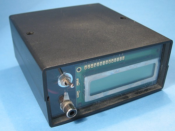
Housed is the frequency counter in a half shell casing. The front consists of polystyrene glass from the hardware store. The LCD display was attached with superglue.

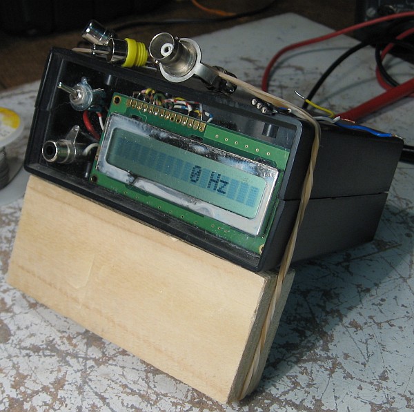
Interior.

Bird's eye view. On the back of the connector for the power supply. The rag pressed the LCD display against the front glass.

The board. The defective transistor of the preamplifier I just clipped without removing the board from the top and a new soldered. This simplifies the repair.

Frequency display. When 1 x 16 dot matrix display I had caught a specimen with poor contrast. That's why I want to replace it with a copy with backlight.

The active probe .
Conclusion: Sufficient accuracy for the low-frequency range and for the repair of AM broadcast radio. The measuring tip of the probe must be kept active only in the vicinity of the oscillator coil or variable capacitor of a tube radios to determine if the oscillator oscillates and if so, at what frequency. When overvoltage usually only the input transistor is destroyed.Otherwise you do with a capital error not broke a lot of money. For accurate calibration of an SSB receiver with a resolution of 10 Hz frequency This frequency counter, however überfodert.