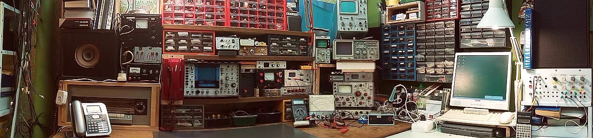
Photo collection of parts and components from old tube radios as repair help – Typical faults that occur in old tube radios
This photo collection is intended to serve as an guideline for the repair of old tube radios. The composition is added in the course of time. If possible, the images are annotated with repair tips and the typical age-related error descriptions. How to repair an old tube radio , is explained under repair tube radios. My repair reports of my little radio collection are also helpful.
Capacitors (paper, ceramics, styroflex): Defective capacitors are the main cause of error in old tube sets. The winding capacitors have as insulation paper which was exposed through the decades chemical changes. The ingress of moisture caused leakage, these leakage currents increase disproportionately to the applied voltage. If these defective capacitors are to prevent, for example, as coupling capacitors, the anode voltage of the control grid of the following stage, they adjust the operating point towards higher anode currents, which in the extreme case, the anode plate of the NF-amp tube (eg EL84) can move in a red glow. Therefore such coupling capacitors must be replaced mandatory. In sound control stages, they ensure an ugly sound. Not in every case capacitors need to be replaced with leakage currents. This depends on what function they fulfill in each case in the circuit.Defective paper capacitors can be personalized with a capacitance meter usually expose indirectly by an increased capacitance value.
This paper capacitors can be replaced by modern plastic film capacitors of all kinds with appropriate voltage strength. In power supplies, they should bear the VDE mark. This is especially true for many capacitors in Allstromgeräten, which are connected without galvanic isolation to the power grid.
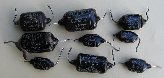
Wima Tropydur, gennant barley sugars are broken almost 100% and show leakage on. If they are used as coupling capacitors, they are definitely replaced.
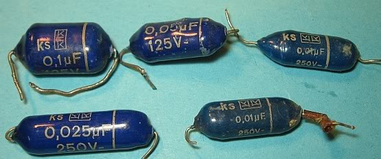
These potted in tar capacitors from another manufacturer have the same problems as the Tropydur capacitors.
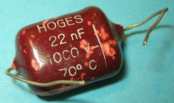
Also this red "cough drop capacitor" heard like all potted in tar types to the problem capacitors.
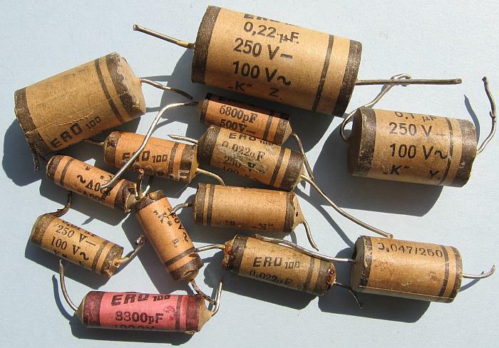
Paper capacitors of the brand "ERO 100" also have almost invariably include leakage and depending on the application in the circuit replaced.
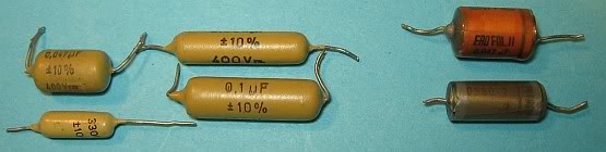
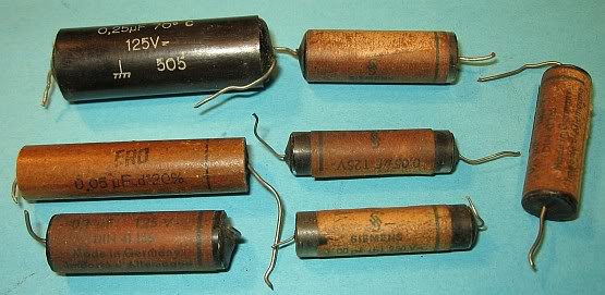
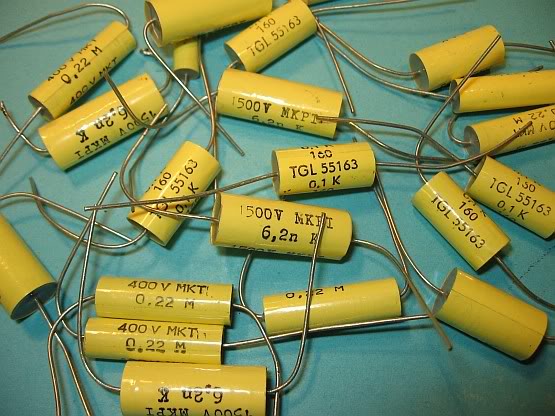
The yellow capacitors left in the picture are mostly fine. The capacitors in the right image are encapsulated plastic film capacitors in resin and should be reviewed at critical points. Mostly they are in order. EROFOL are plastic film capacitors and well suited for use as spare parts. EROID and Wima Durolit are paper capacitors and correspondingly vulnerable.
Links: styroflex capacitors: They are very very rare defective and contained in filters and resonant circuits law. Ceramic tube Kondenatoren are almost indestructible in FM parts they are frequency-determining.. If they are replaced by components with a different temperature coefficient, runs away then in all probability the receiving frequency.
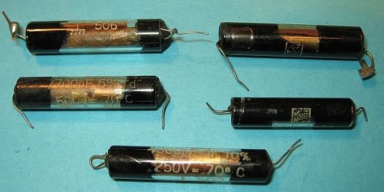
Very old paper capacitors in sealed glass tubes with tar. Mostly, these capacitors have height leakage currents. Such capacitors can be restored by using the tar is melted to replace the actual capacitor with a new one. The old Teermasse is reused.
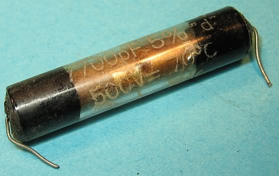
Close-up of a capacitor in the glass tube.
Paper capacitors in sealed with tar tubes of cardboard or Pertinax. Probably 30s to early 50s. The Teermasse can be melted or scratched out here to replace the capacitor eigtenlichen by modern designs (plastic film capacitors).
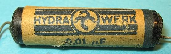
Close up of a 1 nF capacitor branded Hydra. The tube is also sealed with tar.
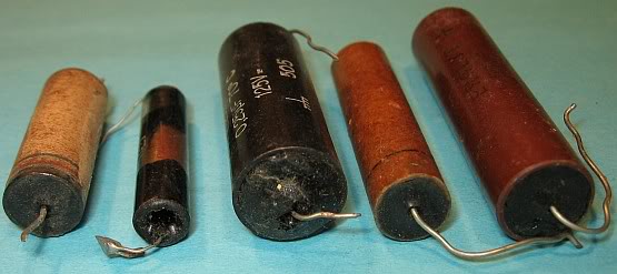
Side view of the "Teerkondensatoren". To restore the grout can be scraped out with a screwdriver. The mass is collected, heated and used again for casting.
This short promotional film by Siemens from the 50s are a little insight into the production of capacitors and on what components make up a tube radio.
Such or similar plastic film capacitors MKT in modern design are often hidden because of their inappropriate appearance in the tubes of old capacitors.
Electrolytic capacitors (electrolytics): Most of them have lost capacity over the decades and therefore are replaced. Filter capacitors can be hot next to a loss of capacity due to high leakage currents and also include replaced. This Sielbelkos can also formed be.
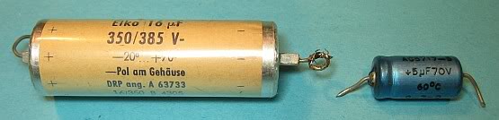
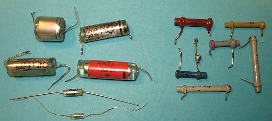
Left: A small filter capacitor, which was probably attached to the screen grid of the NF-end tube. He should be checked for leakage current and capacitance when the radio is booming from the speakers. Right: Elko 5uF/70Volt, as it is used in FM Ratiodektoren. Its positive pole is connected to ground. Has he lost capacity, the FM broadcast sound softly and carried too bright replacement by a Elko entstprechender dielectric strength with values between 5 and 22uF. For large capacitance values are not critical, according to my tests.
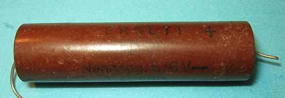
Very old Elko 50 uF with 6-8 volts nominal voltage. It is probably the Elko parallel to the cathode resistance of the NF-amp tube. If this has lost Elko to capacity, the radio sounds quiet and lack bass.
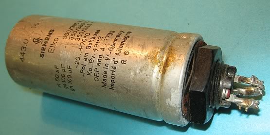
Becherelko for the filter network of a power supply. If it is hot, it is to replace or transform . Buzzing the radio from the speaker, he has lost capacity and must be either reformed or replaced.If he is not hot, new Elko can be connected in parallel to the capacitors alen. Ensure proper polarity and sufficient dielectric strength.
The types of ground: There are two types of hum from the speaker, which may be helpful in troubleshooting. A deep, pure hum that does not become louder when you crank the volume and gets louder when you turn the bass, mostly is due to screening and Ladeelkos of the power supply, which have lost their capacity.
Does the hum a kind of Hall and becomes loud when you crank the volume, then this is due to poor shielding of the NF-shield or a bad ground contact. Fine circuits between filaments and cathode to the NF-tubes may be the cause. Sometimes it was just a bad contact between the tube sockets and its version.
Do not come the hum from the speaker, then he comes mostly from the power transformer. Either plates or screws have loosened or the mains transformer is overloaded for some reason. If it is hot and pungent smell, it has a winding short.
Variable Capacitors: A common problem is stiff or tight bearings from dirt and resin. The axle bearings with a few drops of rust remover provided and leave. No oil can get to the scales hurry. In persistent cases, expand the variable capacitor and at 50 ° C heat in the oven, so that solves the resin. Alternatively, the variable capacitor can be heated with a hair dryer and then in a 40 ° to 50 ° C warm suds (detergent for the washing machine) to be cleaned. Then rinse well with water and dry. It used to be the variable capacitors boiled for 10 minutes in a pot on a stove in water and washing powder. However, this can destroy the plastic parts with newer variable capacitors or can form bubbles the paint in older variable capacitors. Therefore, this method should be used only as a last resort, but almost always leads to success. Fixed axes can also be heated with a thick soldering iron of 100 watts until the resin oozes out. Before, to remove near-mounted plastic parts. With variable capacitors with reduction gears no violence must be used, otherwise the gears are damaged.After cleaning, the bearings must be greased again. Preferably silicone oil can be used, since it can not resinify.
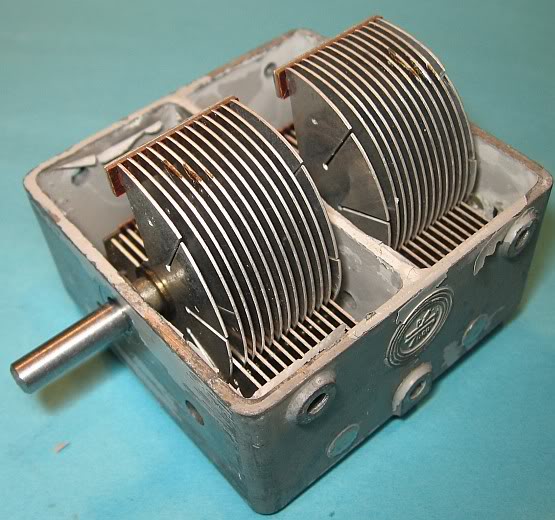
Double tuning capacitor 2 x 500 pF for a heterodyne receiver, in case zinc injection molding. After boiling, the gray paint was peeling off. A plate pack is for the oscillator, the other for the input circuit to suppress the image frequency.
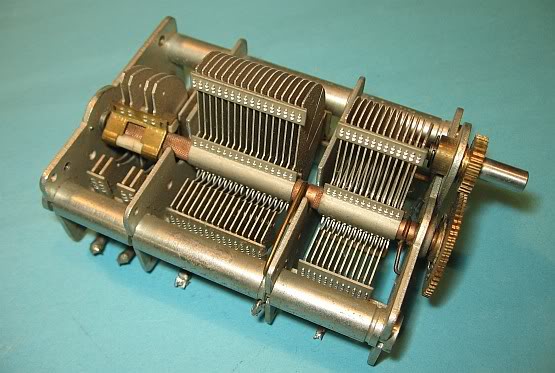
Variable capacitor with reduction gear. The two large plate packages are for long-to short-wave, the two rear for FM. The larger gear is actually two gears, which are braced against each other by a spring so that the transmission has no game.
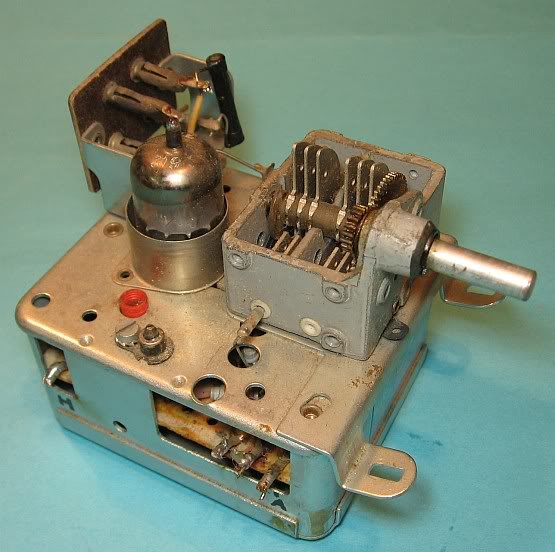
FM tuner with an ECC85. On the shielded enclosure sits a small variable capacitor with double reduction gear.
Resistors: Resistors are high impedance with time. This fate befalls especially the high-resistance carbon film resistors. If in a radio after discharging the filter capacitors the tube radio is completely de-energized, almost all of the resistors in the circuit can be measured without desoldering with the ohmmeter. If a resistor should show short circuit, another wave range should be selected. In rare cases, the resistance must be unsoldered one side. Plays the radio does not correct and the radio sounds too quiet or distorted, then the resistors should be remeasured.

Old resistances of tube radios and TV sets from the 50s to 70s. Resistors with a color code are later date and were from about 1960 to market.
These are also resistors. In particular, can be confused with ceramic tube capacitors both right. When you left the resistance coiled Carbon Track is visible through the paint. Discoloration on the paint indicate a strong Hitzeentwickllung. A brown discoloration still means no defect. Is the paint charred black, the resistance is to be regarded as defective and the cause of the overload is observed. Mostly it is then beaten by a capacitor.
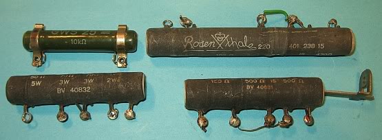
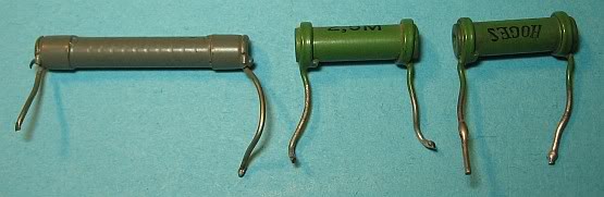
Wirewound resistors for high power dissipation are used in televisions and Allstromempfängern as a dropping resistor for the series-connected filaments. Frequent errors are defective solder joints, which have suffered through the cooling and heating. Or the wire is broken, which is usually visible.
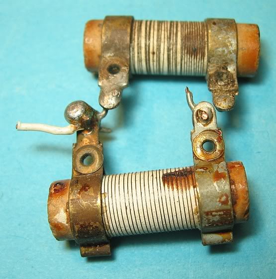
Wirewound Resistors in an open design. The rivets can also be defective and have high resistances.
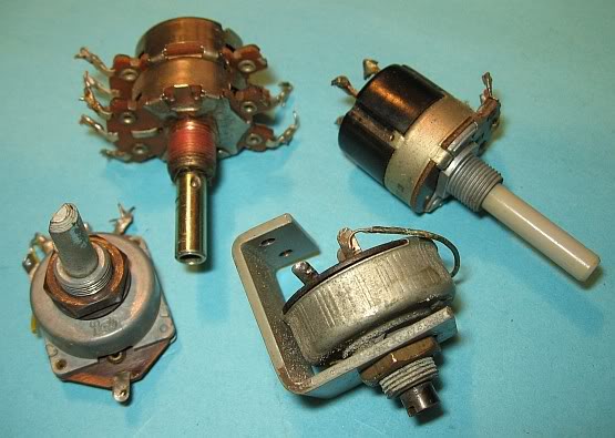
Rotary potentiometer (potentiometer) for the volume and tone control for the often crack during rotation because the slider track is dirty. You have then contact problems and need to be cleaned with contact cleaner. Stiff axes can be treated with penetrating oil. Sometimes the rivets have contact problems, which means that the volume will not quite be rotated to zero.
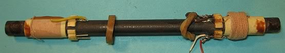
Coils, chokes, transformers and ferrite: These components may also have defects. Coils on long to medium wave may have due to lightning strikes interruptions. LF transformers and power transformers may have winding shorts. Such a power transformer is then hot and pungent smells. The output voltage then drops through the internal short circuit.
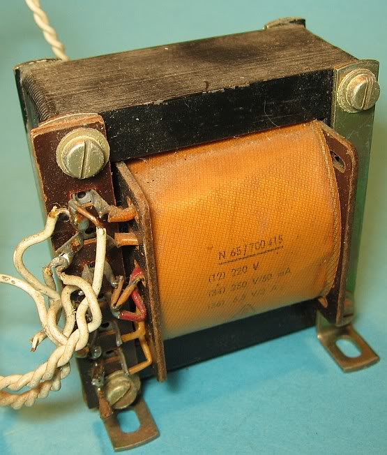
Small power transformer with two secondary windings for the anode and filament voltage. If the surface discolored by change bulbs dark brown to black, this could be a sign of an inner winding short. Incidentally, this power transformer with 50 mA anode current and filament current 2 A is undersized for a normal superheterodyne tube radio. Error-free transformers can reach temperatures up to 50 ° C and more at their sheet during normal operation in the radio.
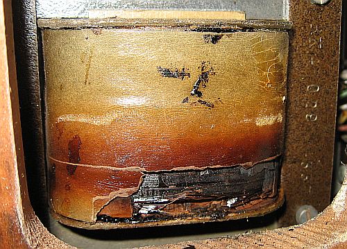
This power transformer was too hot by an inner Windungschluss, which can be seen next to a pungent odor and low anode voltage by a brown discoloration of the above paper cover. Scratch one off the paper, the vekohlte insulation comes to the fore.
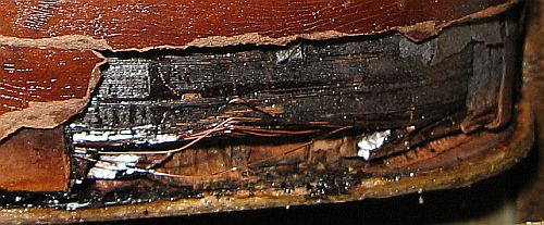
Close-up of charred windings. Either the transformer must be rewound or replaced.
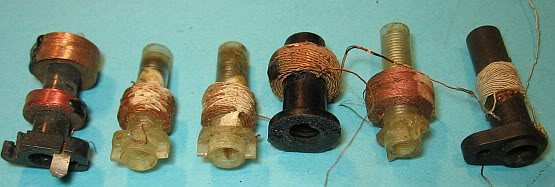
Various coils on long to short wave in cross winding technology with HF wire and matching cores, which is fixed with wax.
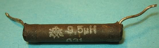
Even at times it was hard tube inductances. This coil of Rosenthal has 9.5 uH.
Ferrite antenna for long and medium wave. Often the ferrite antenna is pivotally positioned to take advantage of the directivity. The thin wires made from HF wire can break off to clean the cabinet.
How to Solder torn HF wire again? HF wire consists of many individually insulated wires to minimize the Skinneffekt. With a lighter burn the insulation until the individual wires glow cherry red and then the red-hot wires are immediately immersed in a thimble with methylated spirits. Then the wires with the soldering iron tin.
Selenium rectifier: They serve to rectify the anode voltage and are usually constructed as a bridge rectifier. Either they suddenly end their life with a stinking rotten egg smell or the voltage drop across diodes their progresses insidiously to ever higher values, so that the power dissipation increases. How to exchange such selenium rectifiers against modern day silicon diodes, is under a replacement for a defective rectifier selenium in a tube radio described.
Selenium rectifier can be reproduced by art circuits with MOSFETs or Zener diodes. More is under selenium rectifier: replacement by MOSFET circuit described. There are also a lot of background information can be found.
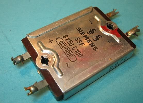
Selenium bridge rectifier in flat package. B is for Bridge Rectifier, 250 means 250 volts dielectric strength, 100 stands for 100 mA maximum current.
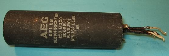
Selenium rectifier in a cup-shaped housing. Some restorers remove the selenium rectifier in the cup to install a new circuit is a silicon rectifiers and filter capacitors.
Electron tubes: It is enough to fill a book. Subsequently, the tube set that was used from about 1954 to the end of the tube era in many tube radios.
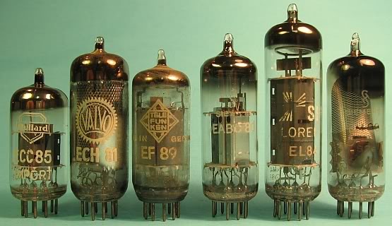
Typical tube set of the E-series from about 1954, nine pole Novalsockeln and 6.3 volt filament voltage. Many tube radios of the middle class were equipped from about 1955 to 1965 with this tube set. Correspondingly similar was also the circuit design.
Common Mistakes of the above tube set from left to right:
- FM double triode ECC85: it is very often responsible for weak FM stereo reception, running away FM stations and periodic switching on and off of the reception.
- Heptoden-triode ECH81: Frequently consumed, poor reception on all wavebands FM to long wave. Consumption is particularly noticeable on FM.
- Regelpentode EF89: Rare consumed. Less sensitive reception on all wavebands.
- Diode triode EABC80: Rare defective. The triode amplifies the NF. Two of the diodes operate in the FM ratio detector, the third diode does the AM demodulation and generates the control voltage.
- NF-Endstufenpentode EL84: Often consumed. Quiet tone and sound distortion.
- Magic Eye EM80: Like all magic eyes almost always consumed and therefore not or only very weakly illuminated. A weakly shining magic eye has no effect on the received power and other features of the radio. Magic eyes are therefore only replaced because they shine so beautifully and provide support for the vote. Due to the high demand they are sometimes quite expensive.
The preceding instructions apply also to similar tube sets earlier model years.
Tubular keys: Using the tube designation can be achieved by the tubular keys to find out much about the tube. All tubes that start with E, have a heater voltage of 6.3 volts. Starts with U to the tube, it has 100 mA heater current us comes in Allstrosmgeräten used. Another letter: C means triode. L = output pentode, F = HF pentode. Example: EF80 = RF pentode with filament voltage 6.3 volts. PCL86 = pentode and triode with 300 mA heater current for television. All tubes with the numbers 80 to 89, nine pole Novalsockal. With the help of the tubes the age of a radio can be determined quite accurately.
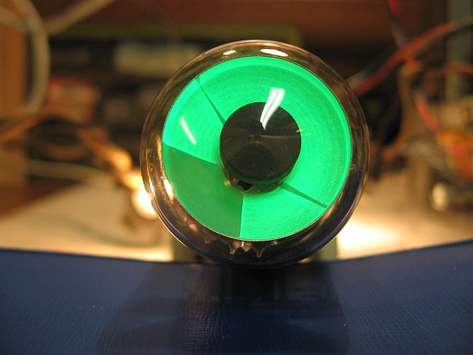
The "magic eye" usually have an old lamp layer and therefore are no longer lit only faintly or at all. At the reception quality have the "Magic Eye" no influence, but only provide a nice visual effect. Unfortunately, these tubes have become very expensive. By remodeling other types can often be manufactured in Russia, which cost less money. If the anode voltage is too low, the magic eye lights too weak. Often too low anode voltage is applied to a spent selenium rectifier.
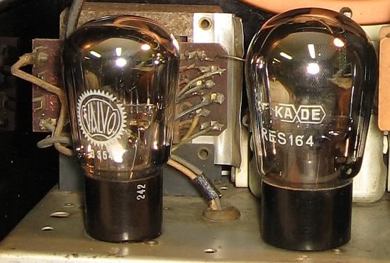
The glass bulb of older tubes are provided with sockets made of bakelite. These connectors were originally thought to be glued with water and glass to become loose. Many restorers use for sticking a few drops of thin liquid superglue because it easily penetrates between the crack of the base and the piston. Some warn that the glass bulb could be tense and tear during curing of the cyanoacrylate adhesive. It is well understood that such tubes may be touched to pull out of the socket just below the base. Those who do not know can destroy the rare tubes.
Socket or socket? The base is an integral part of a tube. The base has pins or contacts, which are inserted into the socket, which is fixed on the chassis or on the circuit board.
The base is broken off or wobbles: The wires coming out of the glass bulb, may be soldered to the pins again. The base, which is usually made of bakelite, can be glued again. Which adhesive is suitable, is almost an issue. In an old film bakelite resin was used as adhesive. So I would not shy away from epoxy two-component adhesive.
In the base it rattles: These are broken remnants of the glue, which not disturbing.
Such brown to black scum or streaks on the inside of the glass envelope of electron tubes usually occur at low frequency output tubes or power tubes in televisions. These streaks are a sign that the tube has been used very many hours of operation. Whether it is already consumed, it can not be read. The effect is called electrolysis glass and does not affect the electrical state of the tube. This tube is the way, in perfect order.
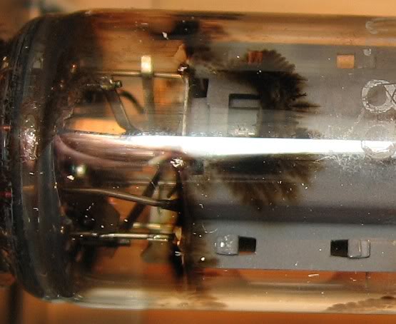
A reflective surface on the inside of the glass bulb of the vacuum tubes is normal, and is derived from the getter forth. The getter is to improve the vacuum within the tube. If the latter pulled air, the getter oxidized to a white and milky coating. The tube is then unusable.
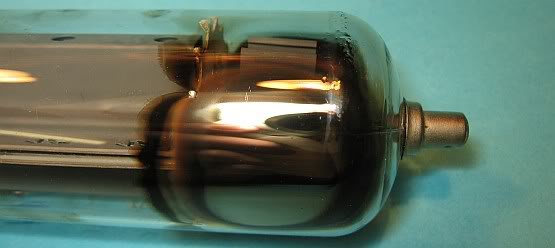
The getter is reflective on the inside of the glass envelope of an electron tube is as normal here on the screen indicating that the vacuum in all likelihood is still in order. If the getter clouded milichg-white, the tube has drawn air and is defective. On the way, is a PL509 to see what was used in-line amplifiers of color televisions.
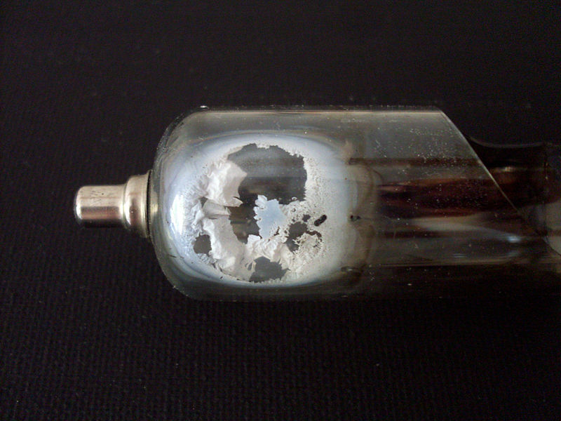
If the otherwise reflective getter oxidized on the inside of a tubular glass flask and clouded milky white, the tube has drawn air and is defective. A broken glass bulb is of course an extreme example (Image source: Wikipedia , Author: Corvintaurus ).
Other parts: scales lamps, neon lamps, switches, sockets and other components.
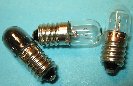
Scales lamps with E10 socket for 6.3 volts and 300 mA current. 6.3 volts corresponding to the heating voltage of the tubes of the E-series. The left lamp is burned out. In Allstromgeräten with tubes of the U-series, for example, all the filaments and the scale lamps are connected in series. It flows through a current of 100 mA. Therefore, scale lamps must be in Allstromgeräten replaced by those with the same current and voltage values. Burns a scale lamp in a Allstromgerät through the whole radio is dead, since no current can flow through all filaments.Unfortunately, there is a new scale to lamps with short life in the market.
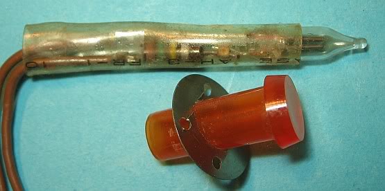
A neon lamp with resistor (150 ohms), which is operated directly on the system voltage. They have been used less frequently. She probably comes from an old TV set. Defective glow lamp will not ignite. Glow lamps have a limited life.
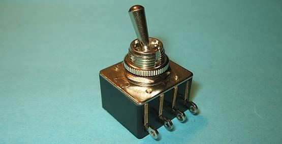
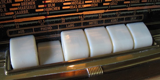
Toggle switch of this type, which are still manufactured, are also located in old tube radios as a network switch, which is often folded about the mechanics of the keyset.
Toggle switch in old tube radios come as a network switch for use. You have only a slightly differently shaped rocker arms as in the figure above. This rocker arm is moved via a mechanism which is actuated when the "bite radios" with the key set. Often the switches inside dirty or gummy, which is why the radio does not turn on. Remedy: penetrating oil (rust remover) hineinträufeln, actuate rocker arms several times and wait a few days until the device is connected to the power outlet. Before turning to the flammable vapors must have dissipated in the switch, so the switch is not damaged by the Einschaltfunken triggered small explosion. Inside the switch is a metal roller which is moved by a lever and closes the contact ( picture of a similar construction from Wikipedia ).
Key sets and switch shaft: corrosion and pollution are more than 90% the cause of mechanical and electrical problems in the form of clamping buttons, momentary buttons, bad contacts and leakage currents. Some wavebands are not or are not affected. Solved can be removed by contact-unr cleaning sprays to corrosion, dirt, grease, and resin such problems almost always. A thorough cleaning can be with a lot of brake cleaner, which must be free of acetone, however, achieved. Other causes may be mechanical wear. As key sets and wave switches are again made to work without having to remove them equal, see " wave switch and key sets of old tube radios repair "described in detail.
Soiled contacts of the key set of "teeth radios" from the 1950s and 1960s, giving rise to a variety of errors. Some wavebands do not work or are almost numb. This helps to open the device and from above and below the spraying with electronics cleaning spray and RF contact cleaning spray. The keys to move until the dirt is gone. If the set of keys hooked or stuck, it is always almost verhartzen joints, which are unjam by said means. The keyset can also pinch when keys contact with the cabinet. Then the installation of the chassis to adjust. In one case, the OFF button has not be pressed down far enough. A washer to the lower attachment of the chassis made remedy. The plastic keys are often made of polystyrene. If they are broken, they can be glued with UHU plast, which is actually a solvent.
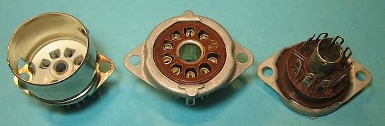
The contacts of the tube sockets can corrode and be the cause of a variety of possible errors.
Due to the possible corrosion of old tube socket or connector pins of the tubes solllte you pull all the tubes before turning on an old radio and plug in again. Possibly can be used for high frequency circuits suitable contact cleaning spray. Caution: On hot tubes you burn your fingers. No hot tubes with liquids of all kinds sprinkle the otherwise shatter the glass bulb.Tubes, which have a press fabric base, always touch the base to pull out. Is still hard pulling, can be helped carefully with a screwdriver blade between base and holder. Otherwise, the glued base from the glass flask dissolves. This is for example the people recipients of the case. Do not touch the tubes at the top, as these can break off and air from entering the flask, so that the display is unusable.
Cold solder joints: Whether a solder joint is defective, is not always apparently visible. The mistakes like loose contacts noticeable. Shaking with a wooden stick and you knock on the components to help them get on the track. Or you knock and presses directly with a islolierten screwdriver on the suspect solder joint. Cold solder joints are often where vibration and mechanical shocks occur, for example, near wave switches. Even where the solder joints by cooling and heating expand and contract, occur more frequently in cold solder joints.
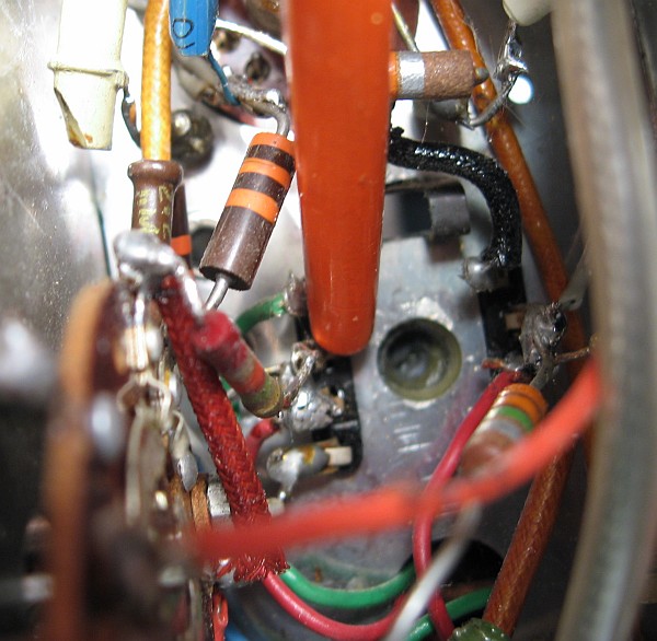
Here is a cold solder joint at the IF filter was Duch tapping and pressing tracked with a wooden stick after the Kontake the wave switch were first suspected. After resoldering the loose connection disappeared.
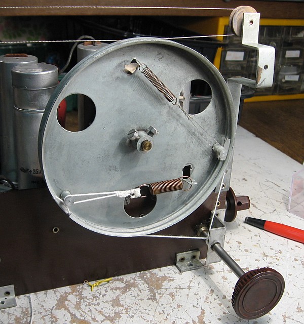
Age-related tear or slip these scales rush very often and need to be replaced. How does it work and what is suitable as a dial cord is under tips and tricks for laying cables scales described.
Totally dirty chassis must be cleaned, as the filth fire hazard, unpleasant odors, leakage currents, a hard working mechanics and electrical contact problems caused. Usually sufficient to clean with brushes, cotton buds and many glass cleaner. More for cleaning is here described.