Measuring instruments and test equipment for the hobby electronics and for the repair of radio receivers
What you need for measuring and testing as an electronic hobbyist, depends crucially on where your focus is. Those who work only with audio-technology and digital control technology, requires very different equipment as a radio amateur or radio hobbyist. Generally valid statements are therefore hardly possible. In this sense, this page is meant as a suggestion for beginners and advanced.
Digital Multimeters: Multimeters with LCD display have become commoditized and already available from 5 euros. It is worthwhile for several reasons thereof to create different models to measure so that, for example, characteristics or currents and Spannngen simultaneously. Many of these multimeters to measure the frequency in the LF range, the capacitance and the inductance. All can measure the ohmic resistance. Some can be measured via a sensor temperature. This is particularly useful for the measurement of cooling twills in power semiconductors. Many can check transistors and diodes.
A multimeter should be able to generate a beep for continuity testing at short circuit. The continuity check is really a very common procedure be the repair.

Multimeter various price ranges in comparison when you measure the same DC voltage source. The cheapest devices (left € 5) differs from the most expensive (right, then about $ 100) by only 4 mV at 10 volts.
Analog Multimeter: It has the advantage that one can see the maximum or minimum balance in work better than a digital display. It needs no battery, which entlleert when one has forgotten again off his multimeter. Cons: Relatively low internal resistance for voltage measurements and a lower accuracy, tedious reading.

Analog Multimeter from the 70s with bag.
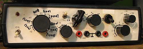
Signal Tracing: This is nothing else than an audio amplifier to make audible the LF signals in a circuit. If an RF probe upstream of the signal tracer, amplitude-modulated RF signals can be tracked and made audible ( description here ).

Signal tracer Build Your Own.
RF probe: who occasionally works with high frequency, requires a RF probe in conjunction with a multi-meter or signal tracer, because the AC voltage range of most multimeter does not work anymore I HF range. RF probes to function in the FM band in and already show a voltage in the mV range on when the probe is held in the vicinity of an oscillator coil. RF probes are needed in conjunction with Wobbelsendern to view by rectifying the frequency response can.
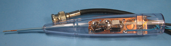
RF probe. As housing is that of an old fever thermometer.
RF probe with two germanium diodes ( data of the probe head to Braubach ). For the examination of tube circuits C19 should have at least 300 volts dielectric strength.
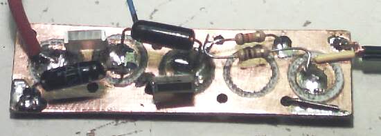
Mechanical construction of the probe on a piece of printed circuit board.
Signalinjektor: This is a small multivibrator in a test pin to systematically examine the various stages of a radio can. description here .
Signalinjektor.
Lab power supply with L200: Who is developing circuits, requires a power source. I had 2 x 5 to 20 volts up to me about 20 years ago a double power supply with two L200 voltage regulators. The maximum output current is approximately 800 mA. In addition, the current limit can be set. Thanks to this current limit and short circuit strength, it is my favorite network device that is virtually indestructible while experimenting and can not do much harm. The disadvantage is that it can not be settle down to 0 volts. By connecting a 5 volt zener diode but voltages less than 5 volts can be generated. The data sheet of the L200 provides many suggestions for the self.

Double power supply with two L200. Voltage and current adjustable. The display must be multipied by 5. Maximum current 800 mA.
Schematics of a power supply with a L200, voltage and current limit can be set. It can also be used other operational amplifier, such as the TL071. It is important to ensure that the maximum operating voltage of the operational amplifier is not exceeded. Under http://www.datasheetcatalog.org/datasheet/stmicroelectronics/1318.pdf there is the datasheet.
Lab Power Supply 0 to 30 volts with current limit: On http://www.electronics-lab.com/projects/power/001 there is the blueprint of a laboratory power supply 0 to 30 V with adjustable current limiting, and a circuit board design. There are read the instructions at the end of the text to incorporate a subsequent limitation of the operating voltage for the operational amplifier. Otherwise, they may be destroyed. In the next few months (as of December 25, 2011) I want to build this laboratory power supply and report on it.
My old Lab power supply 4 to 30 volts, 2 amps: description here . I had built it once in the early 80s.

My old lab power supply that I had built over 30 years ago, still works.

Interior view of my old power supply with fan control and almost only discrete components.
Oscilloscope: In my opinion, an oscilloscope is next to a multimeter the most important measuring instrument because voltage profiles can be viewed in the time domain with him. I own a used Hameg HM 412 dual channel oscilloscope with triggering and a bandwidth of 15 MHz. It meets the most requirements in the repair and construction of receivers up in the short-wave range. The IF of FM receivers can thus also capture. Sure I wish sometimes a bandwidth of 50 MHz or 100, but my oscilloscope shows also still frequencies above 15 MHz, the amplitude being but then decreased.

Used 20 MHz dual channel oscilloscope: Sufficient for most repair work in the workshop. Meanwhile, I've repaired it and recalibrated. The repair report is here .

A Tektronix 454 with 150 MHz bandwidth can also observe an ambitious hobbyists little to be desired: How you can get for about 10 euros for this technological marvel, is in my detailed repair report on the Tektronix 454 The Tektronix 454 was in 1970 one of the most expensive. Oscilloscopes, Tektronix which had on offer. During that time his original price about 4 average monthly income of a family in the United States.
Digital oscilloscope: Meanwhile useful digital oscilloscopes have for the workshop reached a price range that makes it affordable for the hobbyist. Since in a digital oscilloscope important measured values are displayed numerically, obtained on a beat even a frequency meter and a multimeter with them. It also shows other values such as rise and fall time directly. Most digital oscilloscopes dominate FFT, which one has a simple spectrum analyzer. Also, most digital oscilloscopes have a PC interface for long-term observations and screenshots. The upper frequency limit is always to be understood with swabs. It is not valid for single-shots (memory operation) and usually only for single-channel operation.
We noticed, for example, is my Rigol DS1102, a 50 MHz dual channel oscilloscope, which since about offered from 339 U.S. Dollars + customs + VAT will. Customs and VAT are thus added yet. The trick is that this oscilloscope is to be upgraded with a software update from 50 to 100 MHz bandwidth ( instructions here ) (video tutorials: Video1 , Video2 ). Of course void the warranty for such manipulations.
Passive and Active Probes: For measuring the RF range with oscilloscopes are required active and passive probes. A simple active probe for up to about 50 MHz is here described.

Passive probes up to 100 MHz with 1:10 dividers for a two-channel oscilloscope. An oscilloscope is as good as its probes.

Easy active probe with battery for the power supply. Active probes are less capacitive. However, they are only can cope with AC-voltages up to 200 mV.
Function Generator: In the context of an oscilloscope, a function generator is indispensable. Such for audio applications can be personalized with a XR2206, still is in place for a few euros in DIL package in trade, forge a sine-square-triangle generator with little money. There are numerous guides on the Internet. Here are a few examples:
http://www.dieelektronikerseite.de/Projects/Funktionsgenerator.htm
http://www.hobby-bastelecke.de/projekte/signalgenerator_fg.htm
http://www.loetstelle.net/projekte/xr2206/xr2206.php
http://www.elexs.de/sinus1.htm
http://elektro.wienker.org/?p=255
The circuit proposals should be extended so as to obtain a low output voltage setting. Under http://elektro.wienker.org/?p=304 there is a circuit of a power amplifier for such a function generator.
My function generator, which it was the early 80 Janre as a kit, with a XR2206: I've rebuilt it so that it can provide a frequency to 1000 kHz, the sine is however greatly distorted. Also, I have fed more via a series resistor and a pot of the sawtooth voltage of the oscilloscope to sweep with this function generator, the 455 KHz IF receivers can.
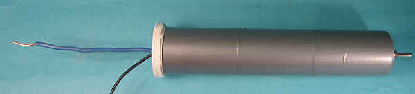
Wobble: Interesting for the comparison of broadcast receivers. A construction project for excitation is here described. A function generator with a XR2206 can be converted to a sweep of the AM IF, in the way of a capacitor and a resistor there a voltage is injected where the frequency is set.
Network Tester (NWT) of the radio amateur magazine FUNKAMATEUR, enables you to display100 kHz to 160 MHz filter curves by using a PC and a software. Even narrow-band crystal filter can be displayed with it. Quality measurements of coils are also possible. With the help of a reflection measurement head and attenuators numerous measurements of RF technology are possible. It is the NWT by a DDS generator and a rectifier IC. My building tips of the kit are here . Under http://www.wolfgang-wippermann.de/there are plenty of examples of measurement.

Completely assembled NWT, which is available now with USB interface. Links the output of the DDS comes out, it goes right to the built-in rectifier. In between, you turn the filter. The output and input of the NWT have 50 ohm impedance.
Capture IF filter curves with a noise generator: sweep transmitter change often too fast when its frequency sweep in order to traverse narrow-band crystal filter can. There is a different method: the filter is supplied by a noise generator. At the output of the filter, the frequency is mixed with a mixer, and a crystal in the LF range. The spectrum can be displayed using the sound card and an FFT program on the computer. The amplitudes of the spectrum so make the frequency response dar. Underhttp://www.qsl.net/7n3wvm/Fil_Meas.html is an example described.
Frequency counter to 50 MHz: These are very easy to build with PICs and dot matrix displays. Under http://www.sprut.de/ … frequency / freq.htm there is a simple nachzubauendes project, here is describing.
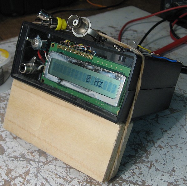
A just quickly built up frequency counter with a dot matrix display which was glued with super glue onto the polystyrene front panel.
 Digital LC Meter: Indispensable in the RF technique to be dimensioned filters and resonant circuits to. It can be measured with wire so that small measurement errors coil of few turns. The capacitance values of a few pF to about 400 pF, this will also capture. There is a ausfühliche instruction with PCB layout by me.
With a digital LC meters can be measured quite easily coupling factors as DG0SA on his side http://www.wolfgang-wippermann.de/koppelfa.htm fooling.
Unfortunately, this LC Meter is suitable for the measurement of electrolytic capacitors, which can be measured by many multimeters but. The quality of coils and capacitors can be personalized with the LC meter also not determined.
Semiconductor testers and component tester: These identify the various types of semiconductors such as diodes, transistors, thyristors and FETs and provide equal nor the pinout. For me, a very important tool. It's not the accuracy, it's about the functional test. Therefore cheap explanation goes from mostly. To find out more see here .
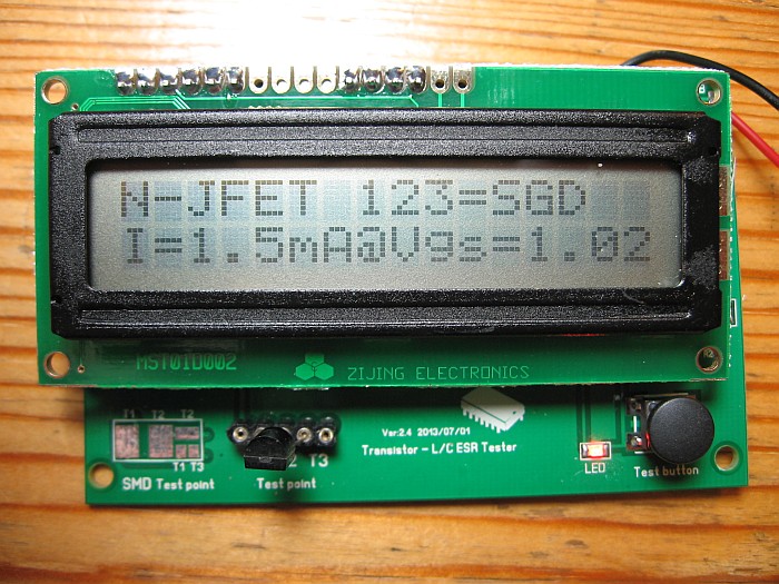
A low-cost components and semiconductor tester from China.
Tube tester: Who repaired tube circuits, nees sooner or later a tube tester. The homebrwing is really worth it here for reasons of cost. My project is described here .

My home-built tube tester.

Examination of a ECH4 from the 1940s on my home-built tube tester.