Lost Place Irbene – A Soviet Secret in the Latvian Forest
22 July 2026 (last updated 24 July 2026)
How we accidentally ended up on the grounds of Latvia’s largest Soviet listening station, stood on a giant parabolic antenna – and spent the following night in a forest near Cape Kolka with no mobile signal at all.
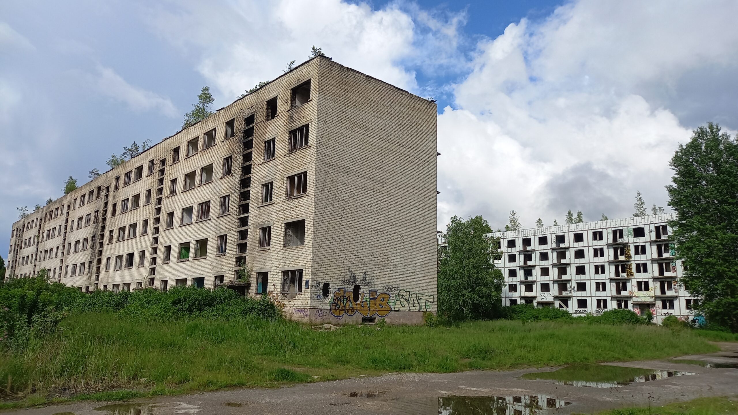
In the middle of the Latvian coastal forest, never marked on any map: until 1994, Irbene was one of the most secret military installations of the Soviet Union – an entire town for thousands of soldiers, scientists and their families, whose sole purpose was to listen in on the West. Today the apartment blocks are decaying in the forest, while right next door a 32-metre parabolic antenna is once again listening to the sky – only this time towards space instead of towards Brussels or Bonn. We had actually only planned to look at the ruins. In the end we stood on a radio telescope dish, walked along a 600-metre cable tunnel, and spent the night in complete radio silence in the middle of the forest, on a rainy June day in 2026.
Irbene had to be built very quickly as a „secret town“ for around 2,000–3,000 people – housing was needed in short order for military personnel and scientists. Multi-storey blocks with standardised floor plans could be erected far faster using prefabricated components than hundreds of individual houses.
What was Irbene? Irbene – named after the nearby Irbe river – was a strictly secret Soviet military town on the Latvian Baltic coast, less than 20 kilometres from the coast at Cape Kolka. Internally the site carried the codename „Zvaigznīte“ („Little Star“) and appeared on no official map – officially it simply did not exist. Construction of the town began in 1946, while the actual radio reconnaissance station was built from the late 1960s onward under the direction of the Soviet Navy.
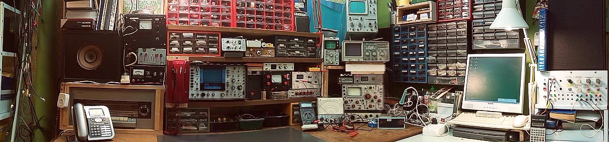
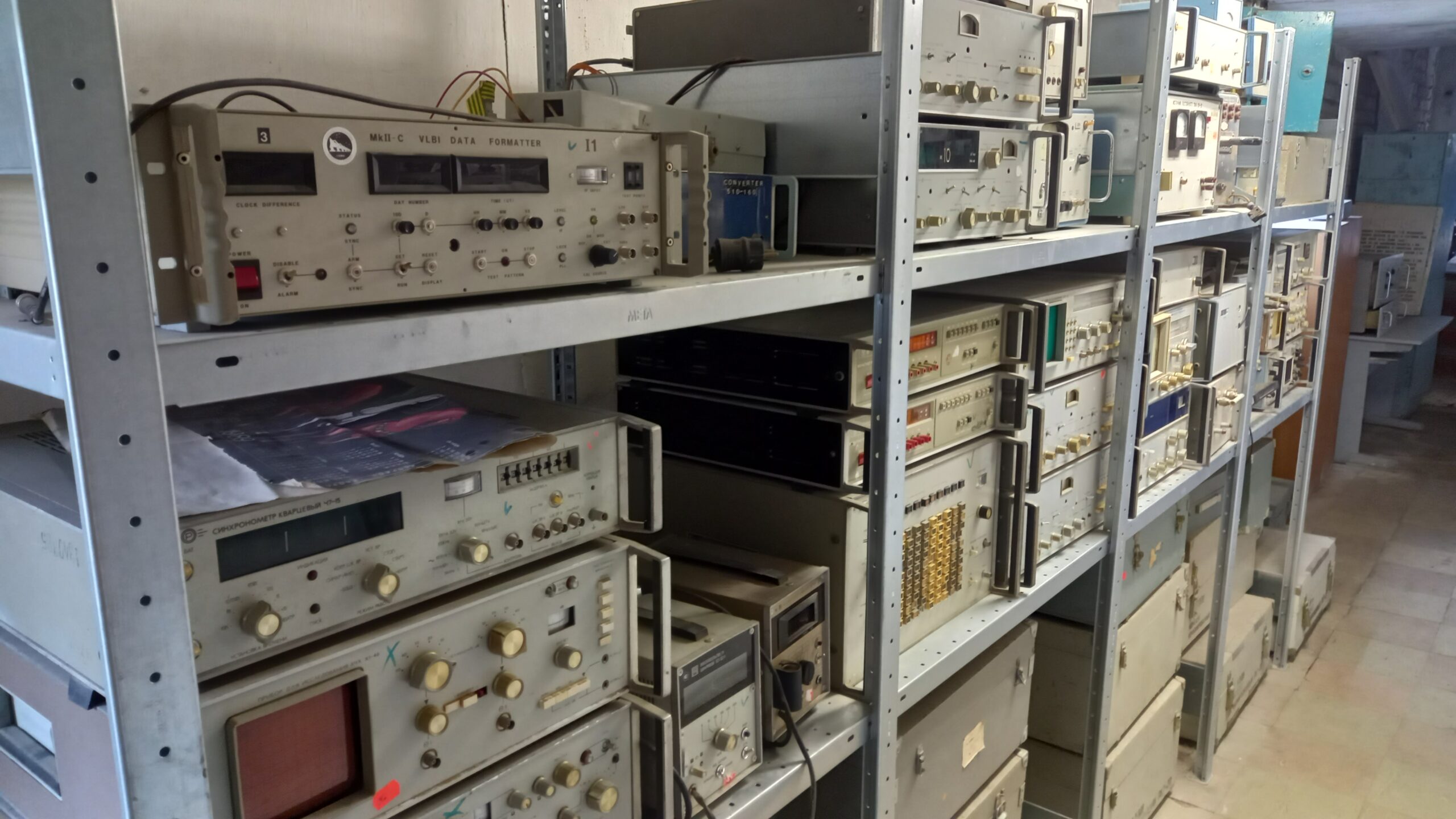
The station’s mission: the systematic interception of radio, telephone and, above all, satellite communications of the NATO states. For this purpose there were originally three radio telescopes of different sizes here – RT-8, RT-16 and RT-32 (the number denotes the dish diameter in metres) – along with extensive signal-processing infrastructure, which we got an impressive look at during our tour of the old measurement-equipment racks.
At its peak, around 2,000 to 3,000 people lived in Irbene – officers, scientists, technical staff and their families, completely cut off from the outside world, with their own school, kindergarten, post office and shop. All personnel came directly from Moscow; not even the political leadership of the Latvian SSR officially knew the place existed.
The end came with the restoration of Latvian independence: in 1994 the Russian army withdrew for good – not without first deliberately destroying whatever could not be taken with them. Cables were cut, drive motors were doused with battery acid, technical documentation was destroyed or removed. The smallest antenna, RT-8, was completely dismantled. The residential town itself was abandoned and has been decaying in the forest ever since.
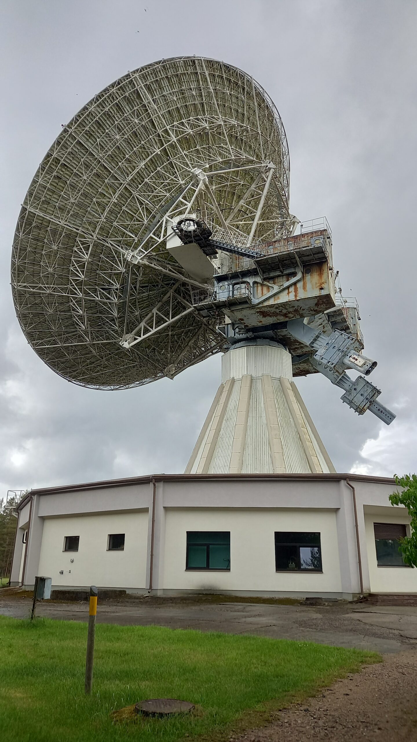
The two large antennas, RT-32 and RT-16, survived – quite literally against the odds. Latvian scientists took over the site, reconstructed the destroyed technology with almost no documentation, and built the Ventspils International Radio Astronomy Centre (VIRAC) from it. The RT-32 – with over 20,000 components, an 80-tonne central cone and a total weight of around 600 tonnes, one of the largest fully steerable parabolic antennas in Northern Europe – today serves radio astronomy, satellite observation and space research. The spy station has become a science centre.
Our visit: We had really only wanted to look at the ruins – that alone promised to be exciting. What actually happened:
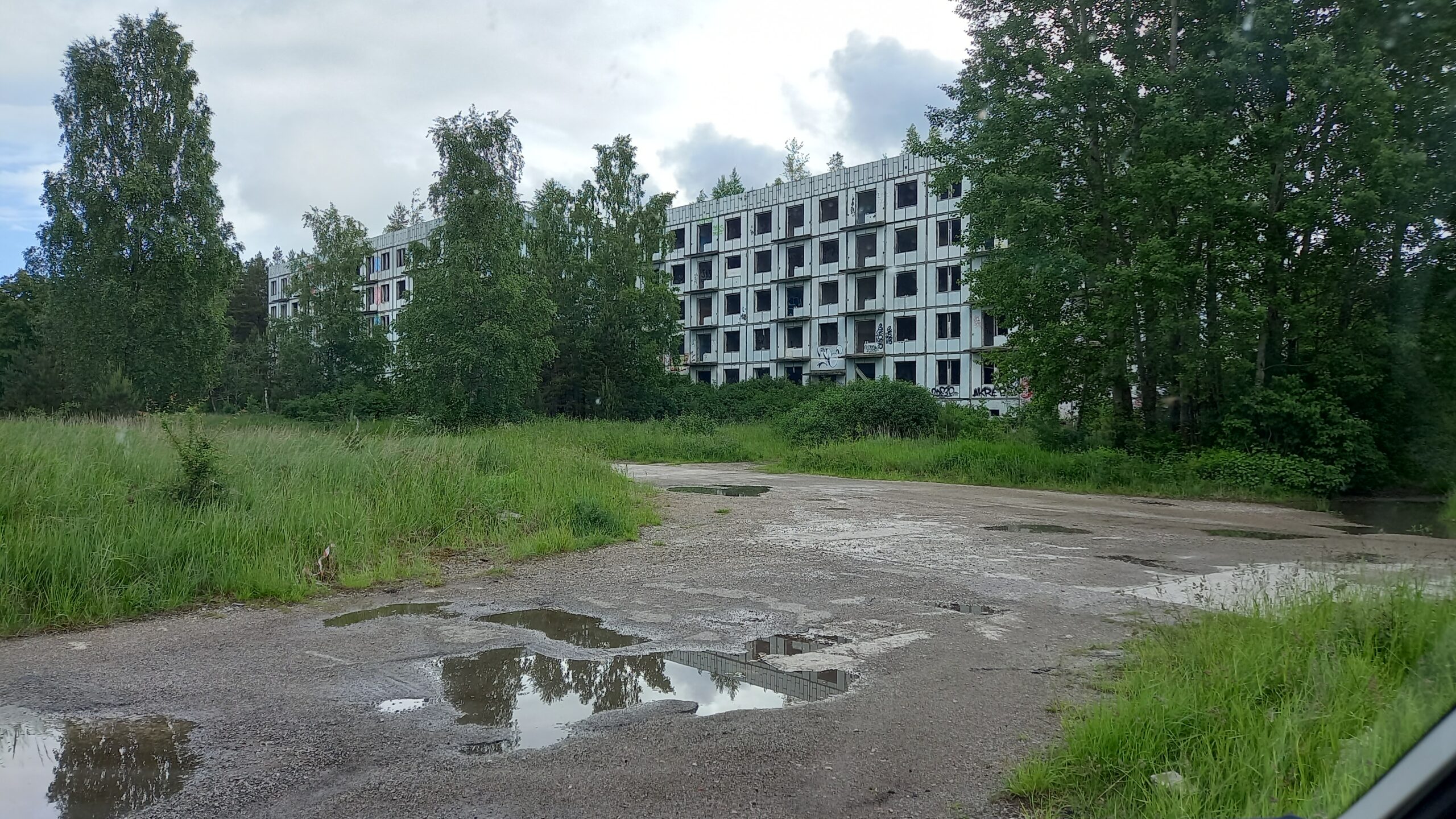
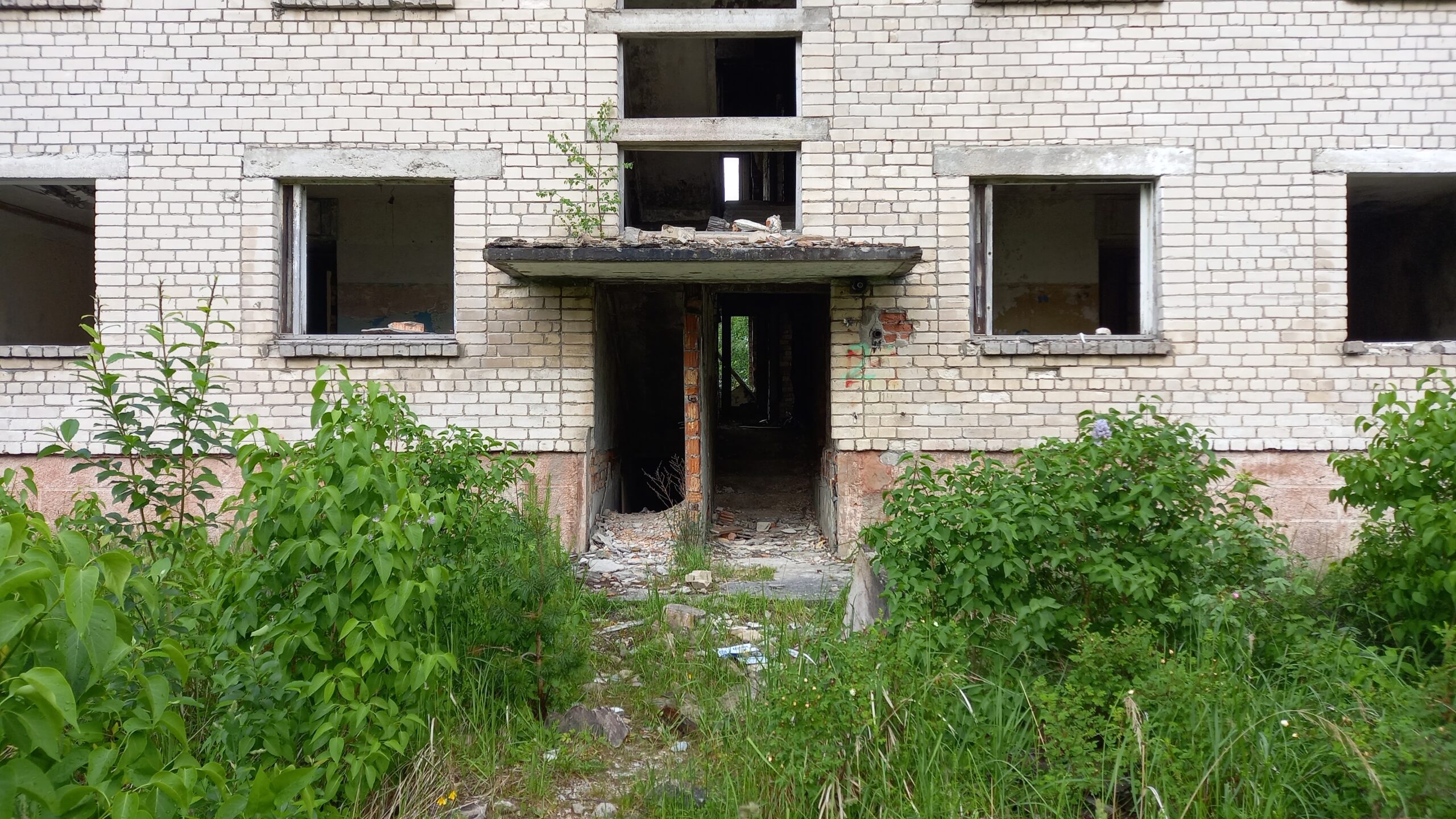
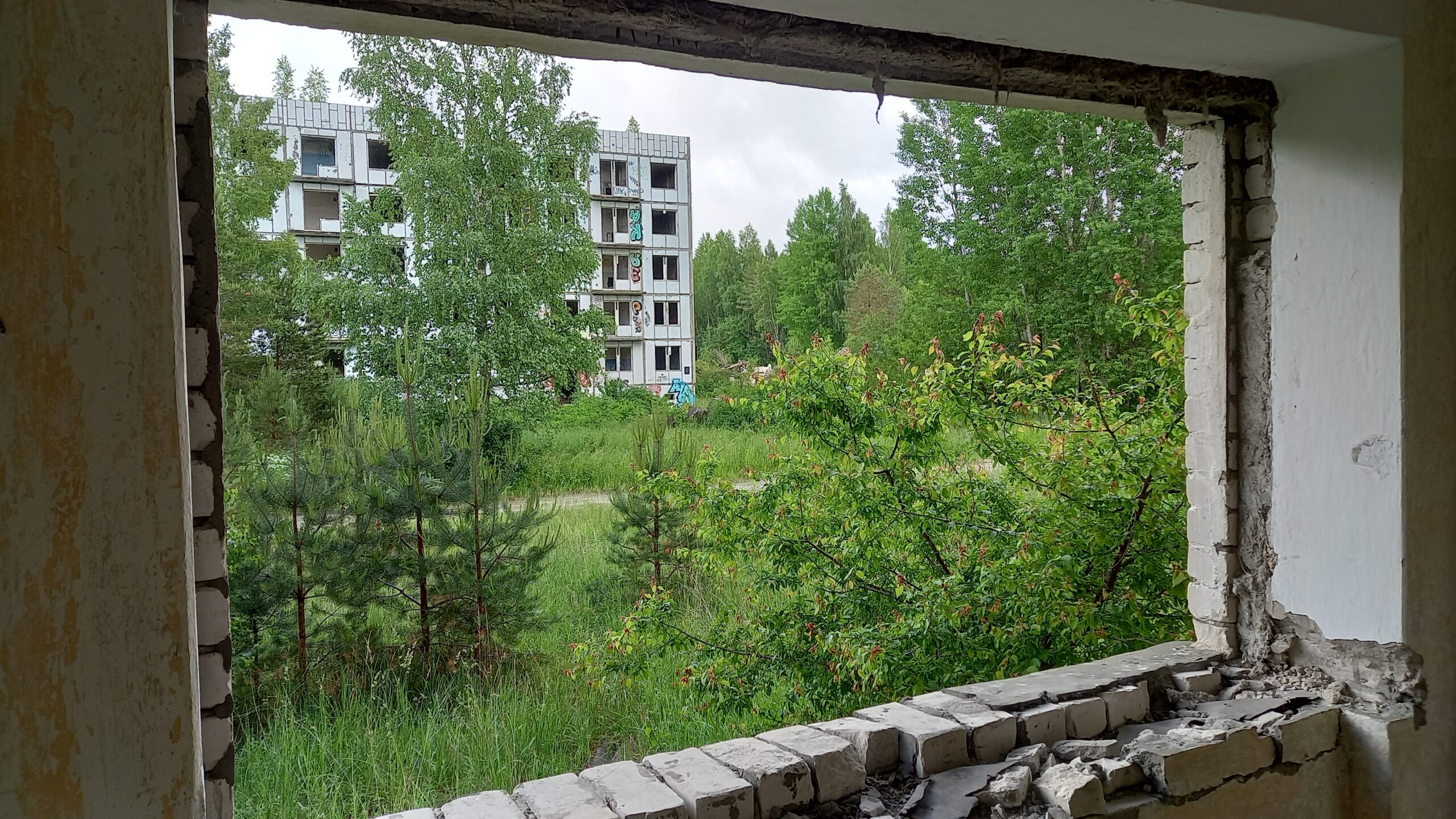
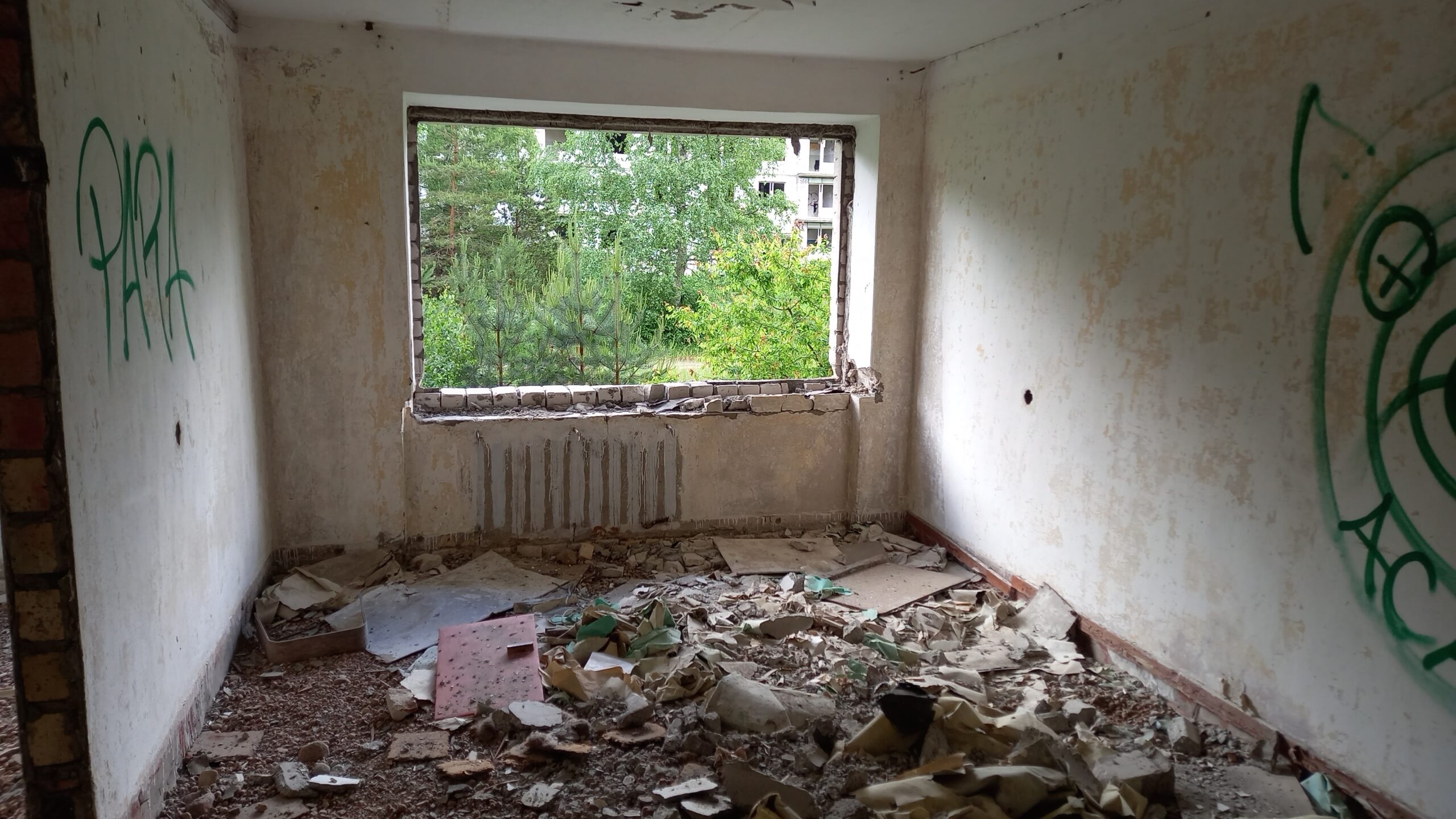
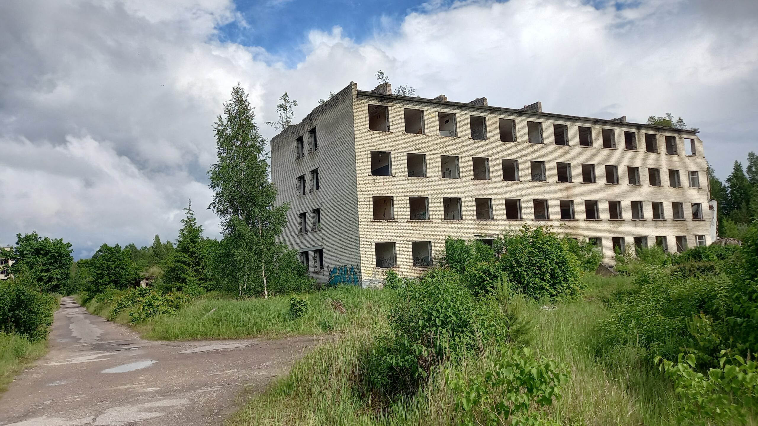
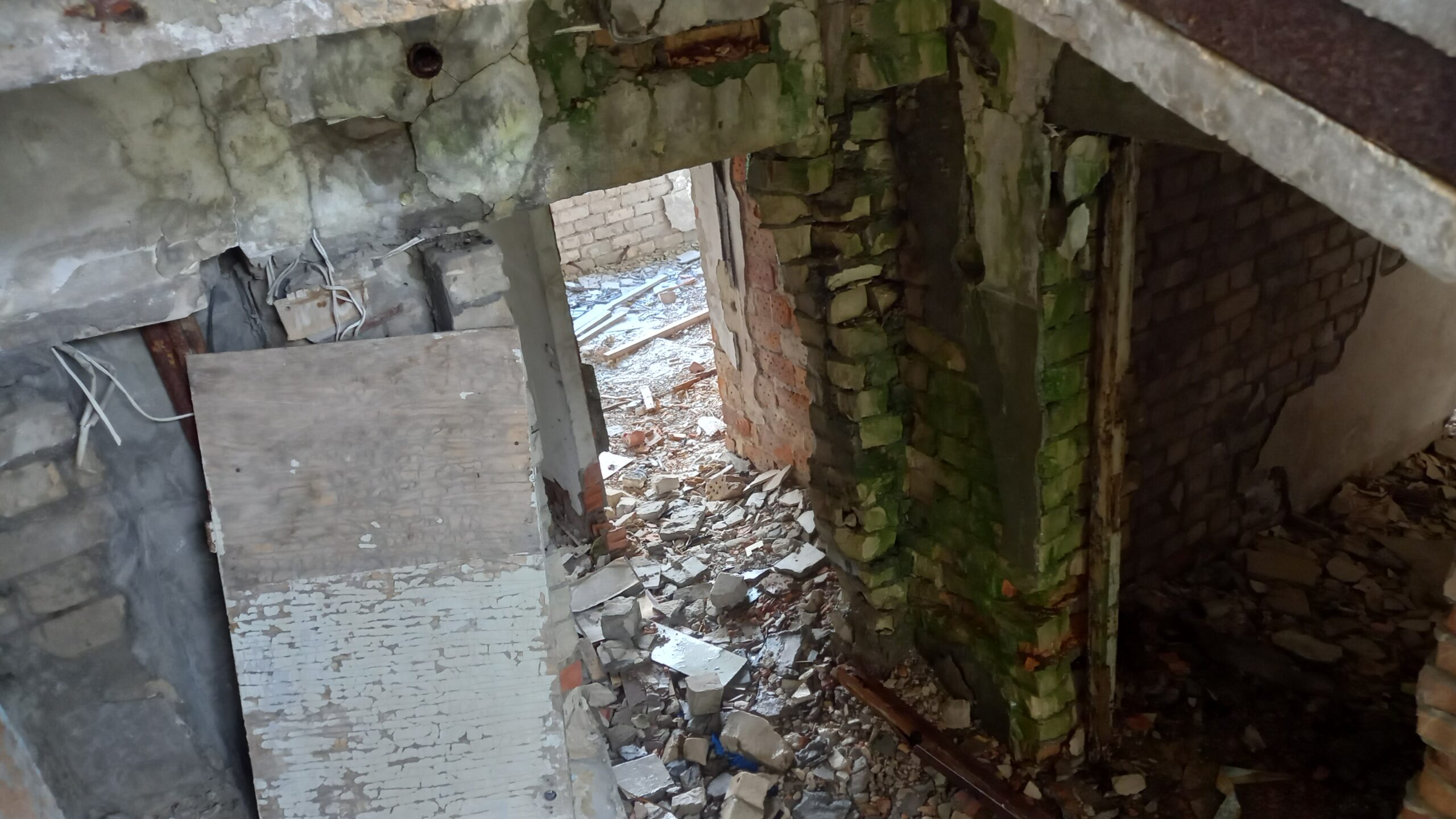
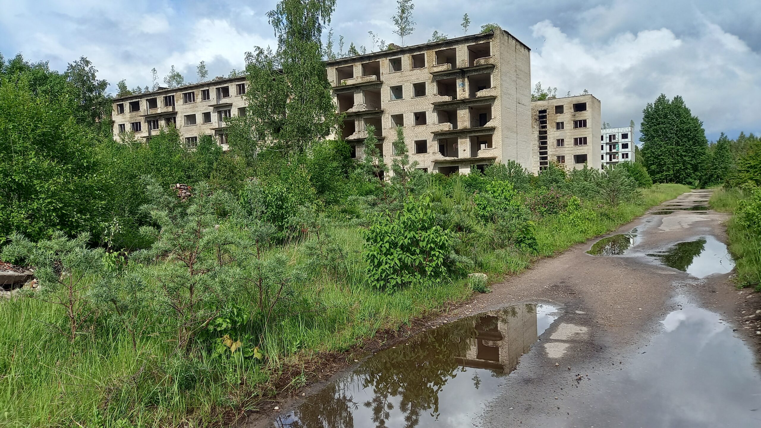
The ghost town first: We walked through the abandoned apartment blocks, went inside some of the buildings, and got a direct sense of how cramped and basic even the flats of Soviet officers once were – bare concrete misery, where today only graffiti and shrubs grow.
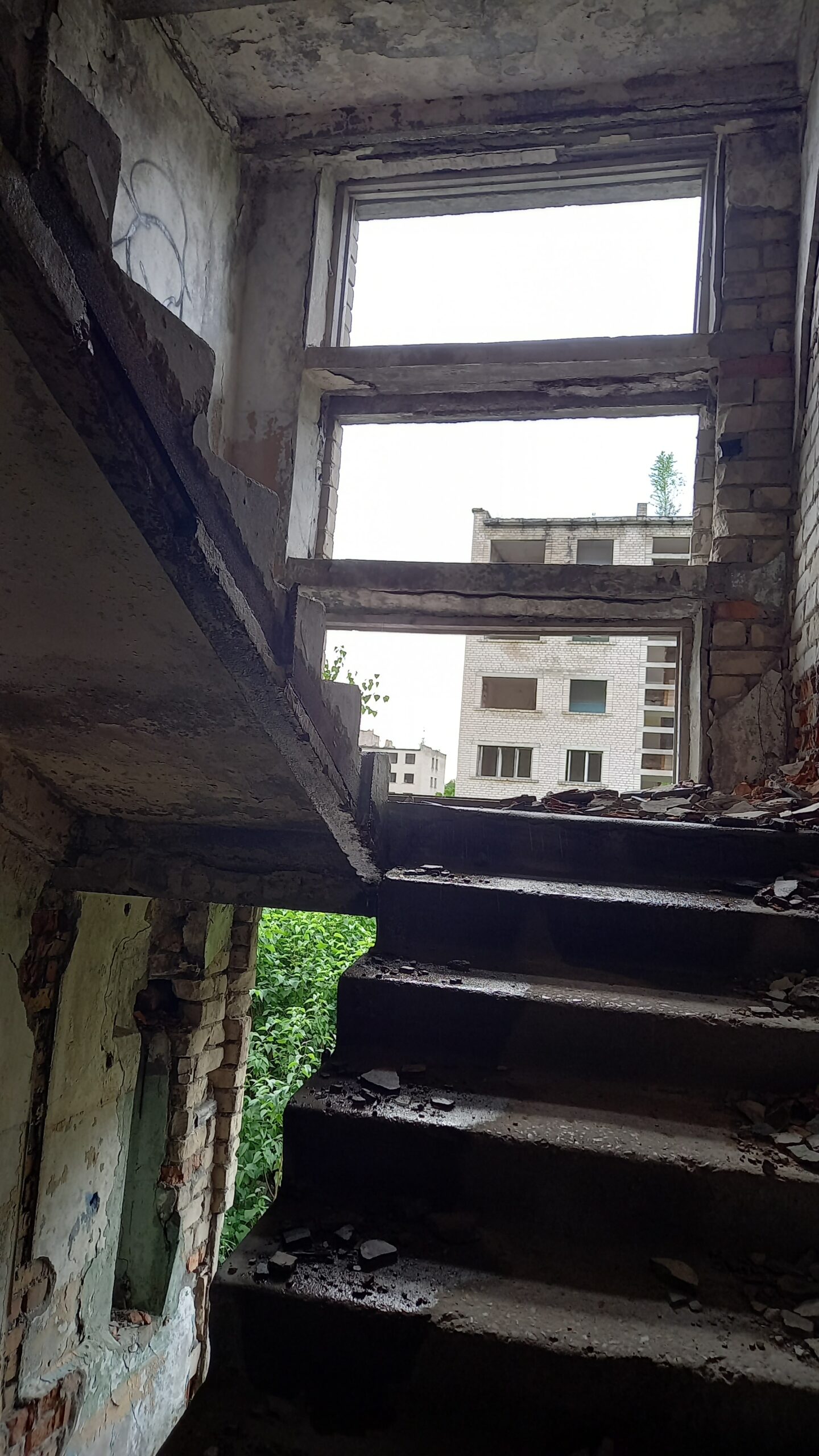
The Soviet Union built to standardised, mass-produced designs practically everywhere in the country (the famous „Khrushchyovka“ and „Brezhnevka“ prefab blocks, or here brick buildings following the same principle). These building plans were drawn up centrally in Moscow and then implemented unchanged across the entire empire – whether in a city of a million people or in the middle of a Latvian forest made almost no difference. Individual single-family houses simply had no place in the system of central construction planning and materials logistics.The ruins are freely accessible. The biggest danger comes from tick-borne encephalitis (TBE) via tick bites.The Soviet social model favoured collective multi-family housing over the „bourgeois“ ideal of the single-family home anyway – private ownership of one’s own house with a plot of land did not fit the official worldview, even where space would in fact have been plentiful. In short: the available space in the forest played virtually no role in the building planning – what mattered were central norms, speed, infrastructure costs, and the controllability of a closed garrison town.Whatever could be dismantled was either taken away or lootedAn administration building?The standardised flats for a family of four averaged 40 to 50 m², with tiny bathrooms and kitchens.What is left of the stairwell.Some of the apartment blocks had balconies
Further along the forest track: As we continued driving through the forest, a sign reading „Visitors“ suddenly pointed into a fenced-off area. The gate stood open – so we simply drove in.
An impromptu tour: No sooner had we arrived than a man came out of the building and offered us a tour of the museum grounds with the parabolic antennas and the old measurement technology. Naturally we didn’t let the opportunity pass. Normally this is only possible for pre-registered groups, and a booking is required. At the start of the tour we were asked to switch our smartphones to flight mode so as not to interfere with radio reception. We were allowed to photograph everything.
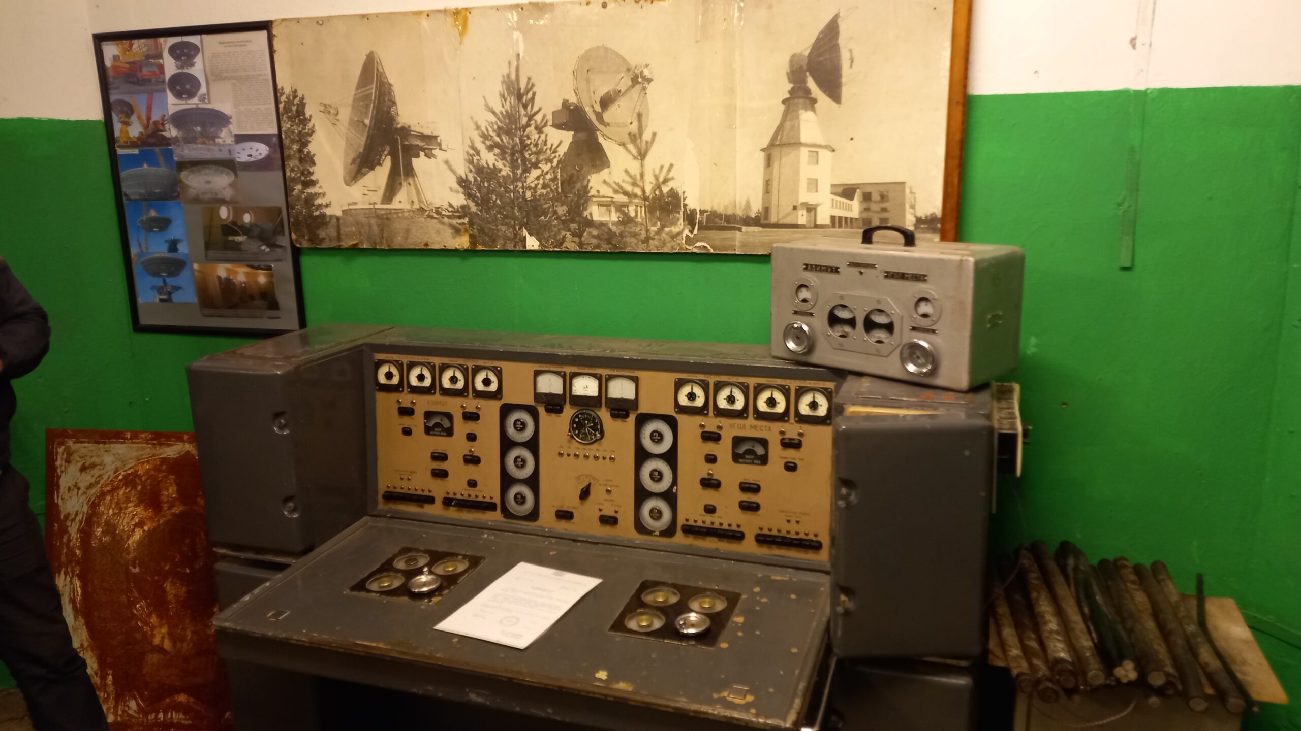
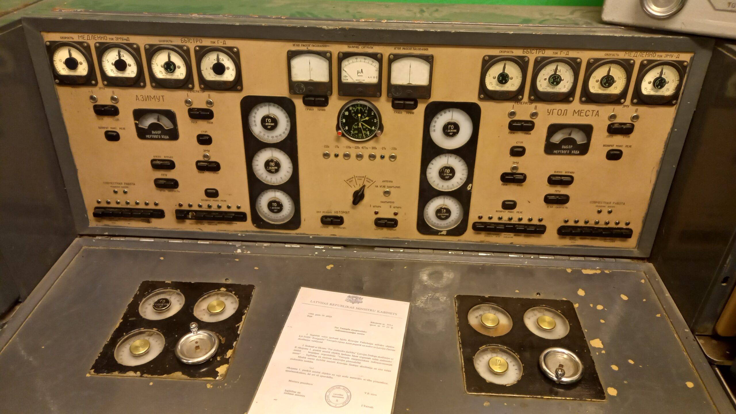
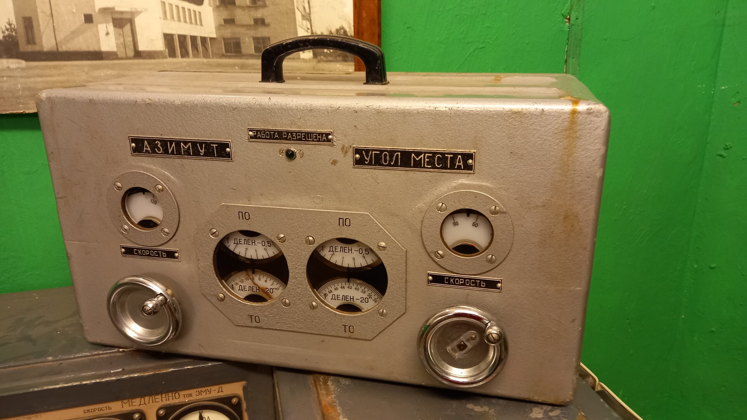
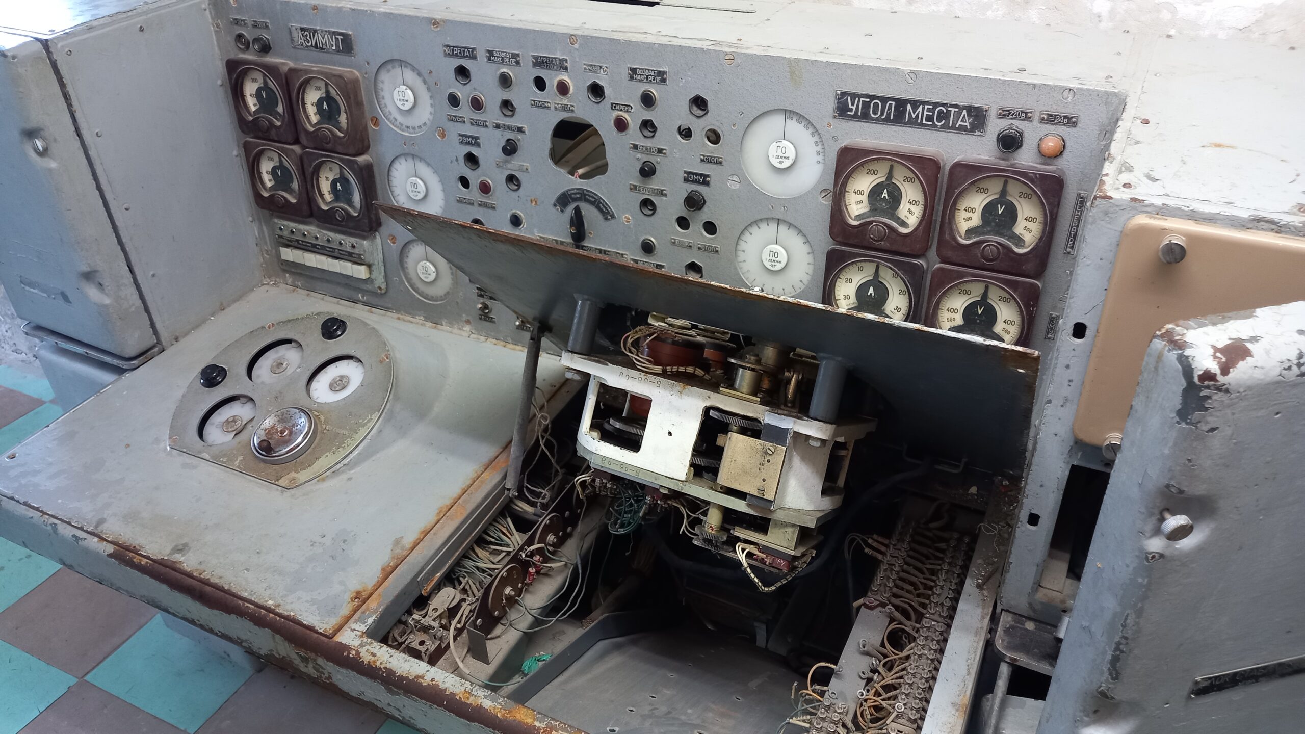
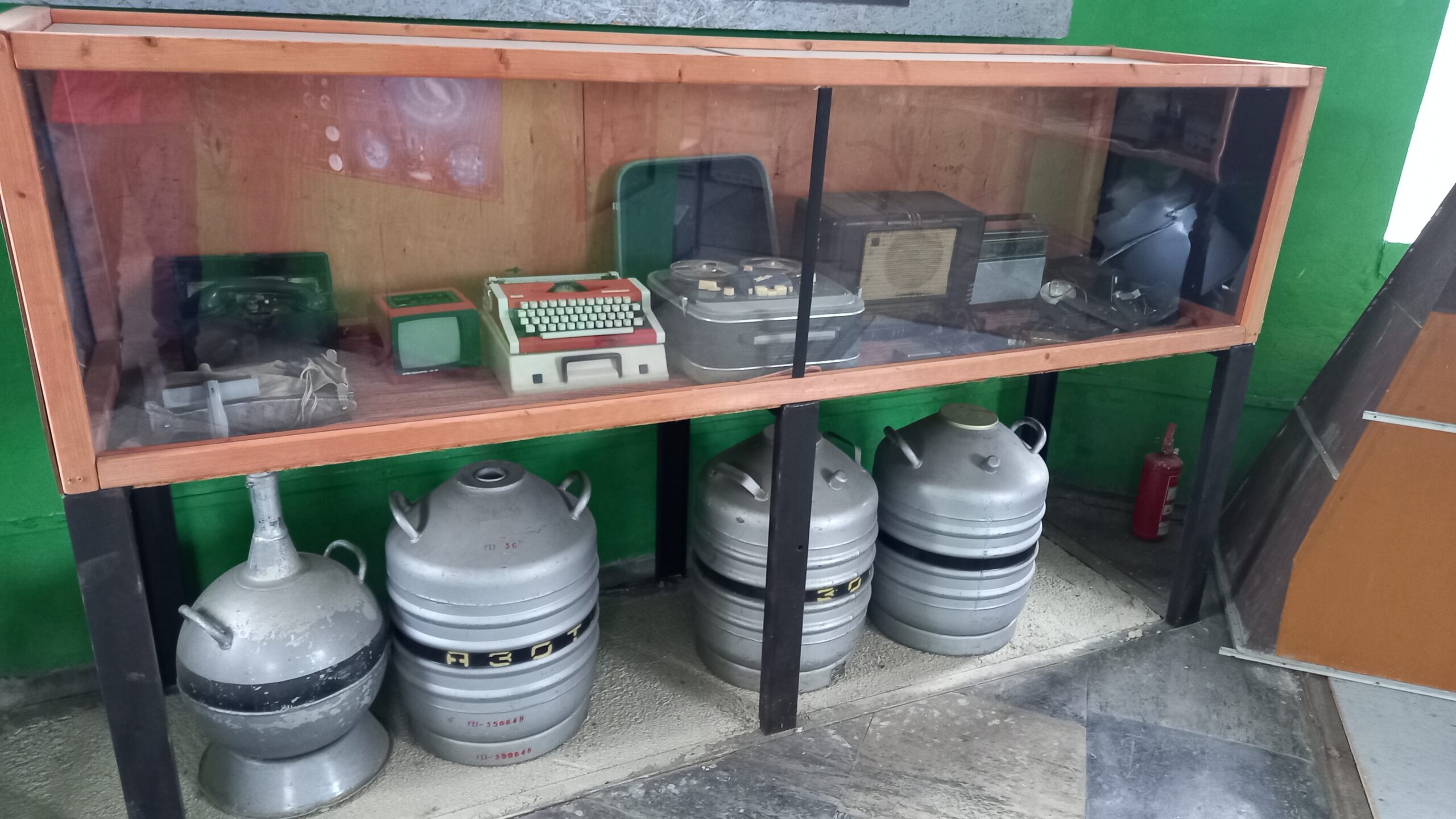
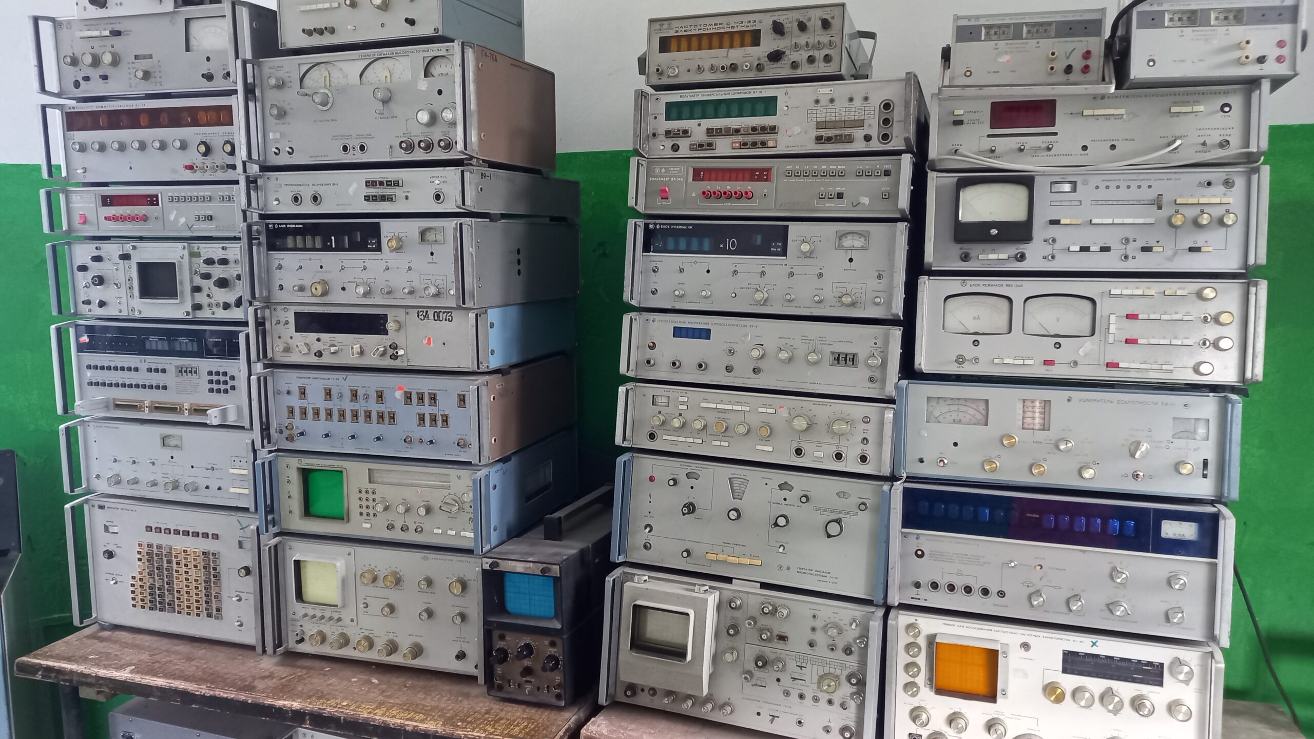
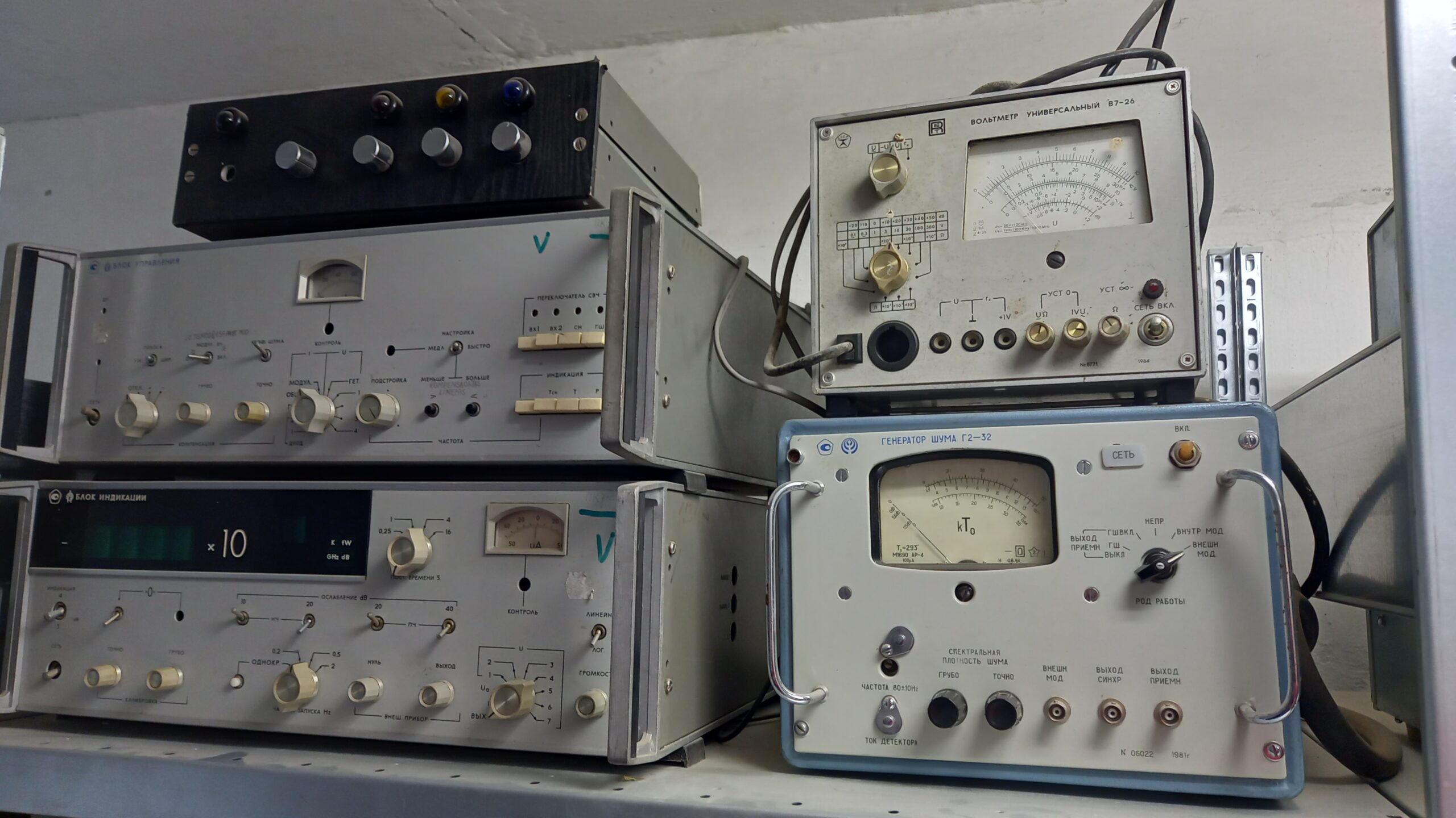
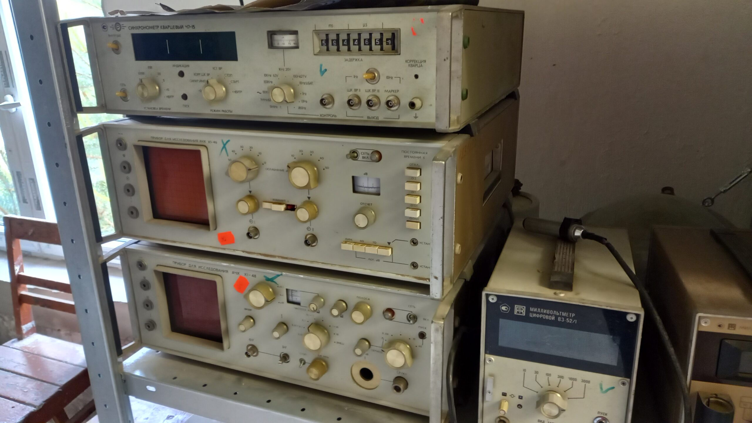
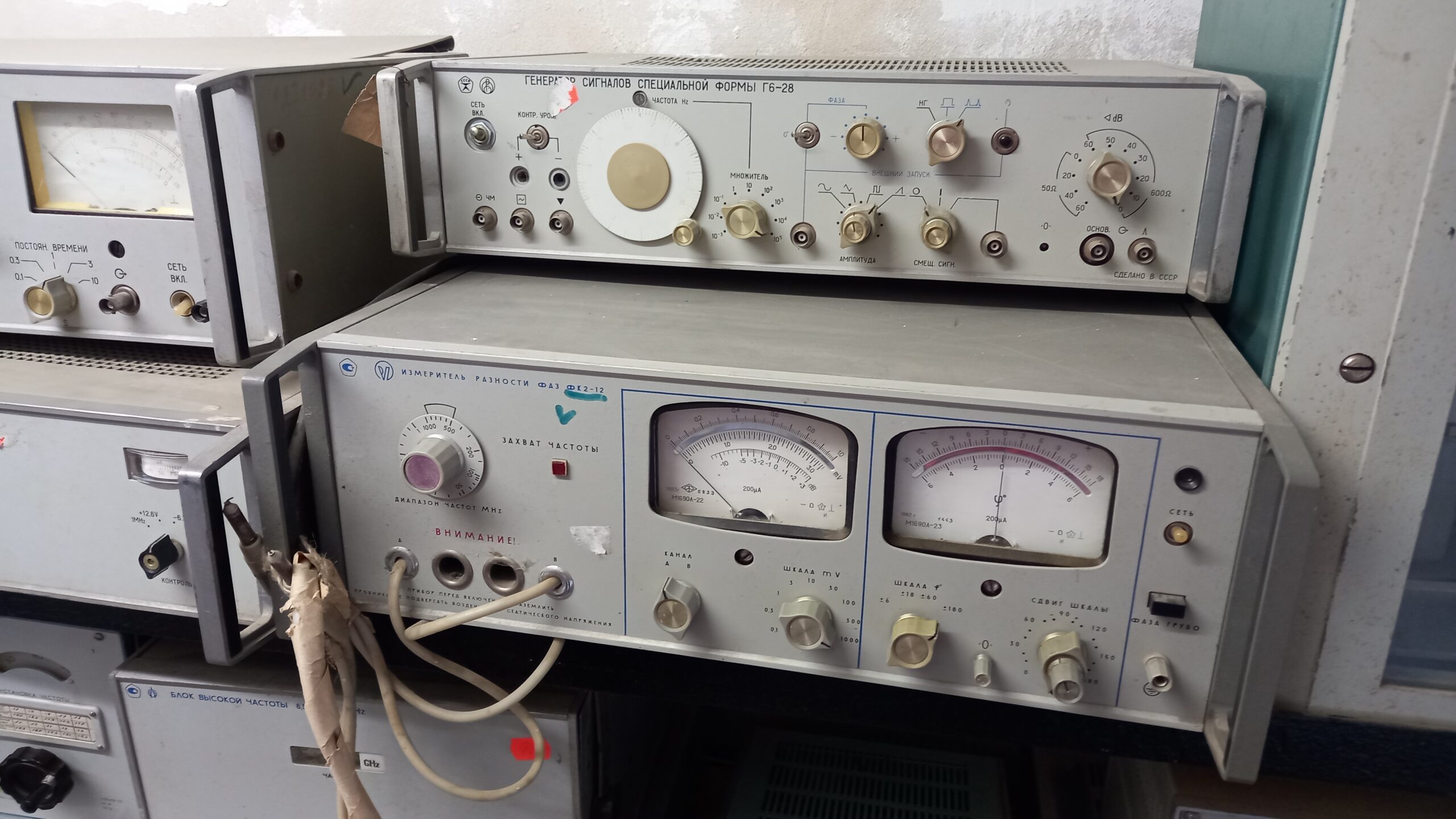
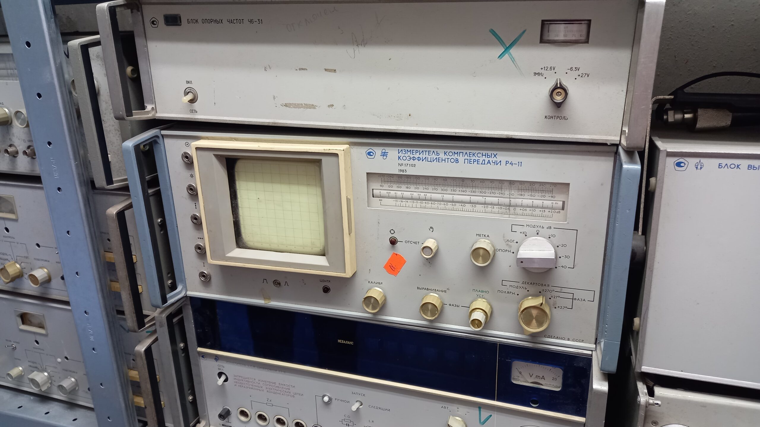
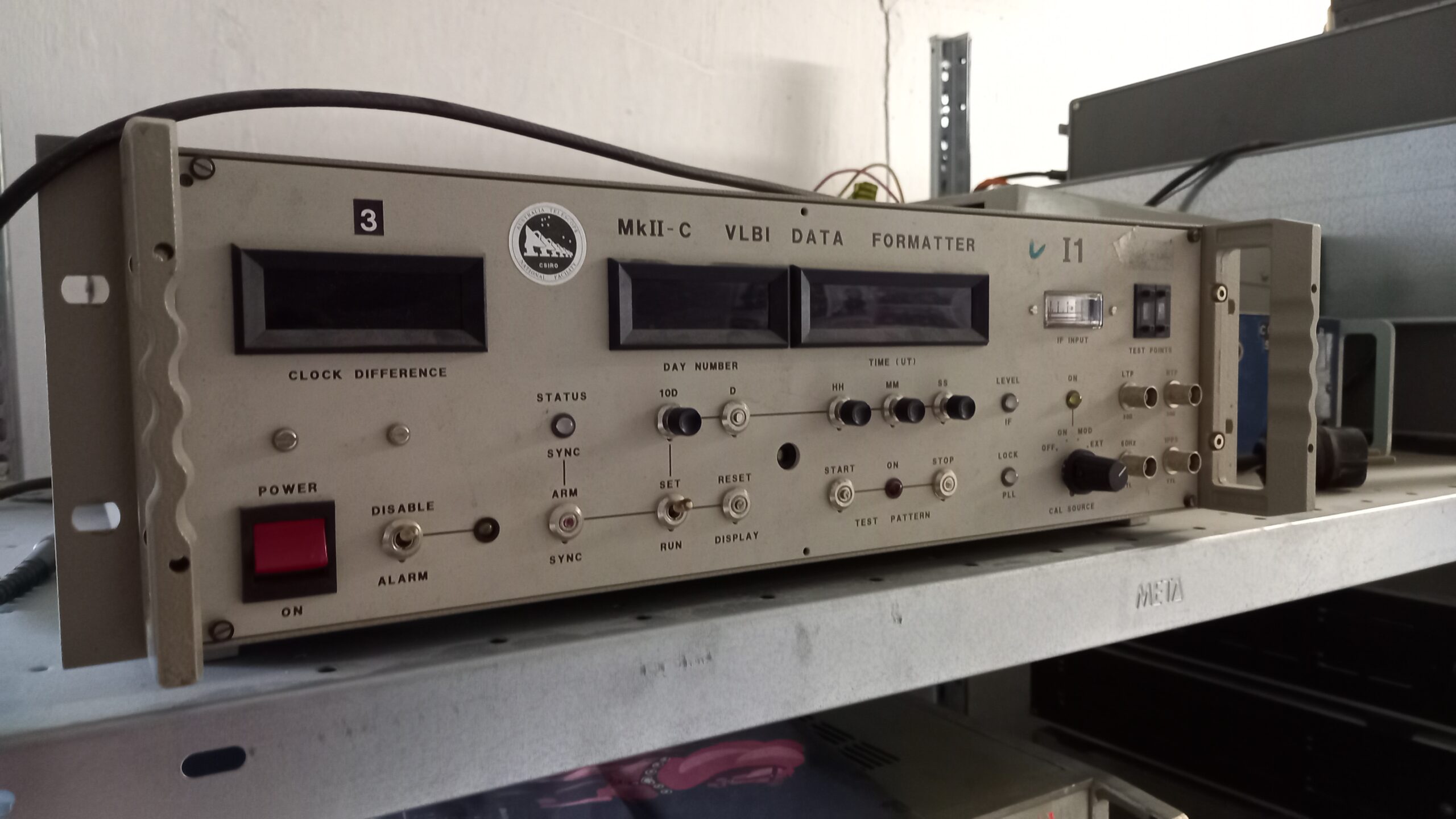
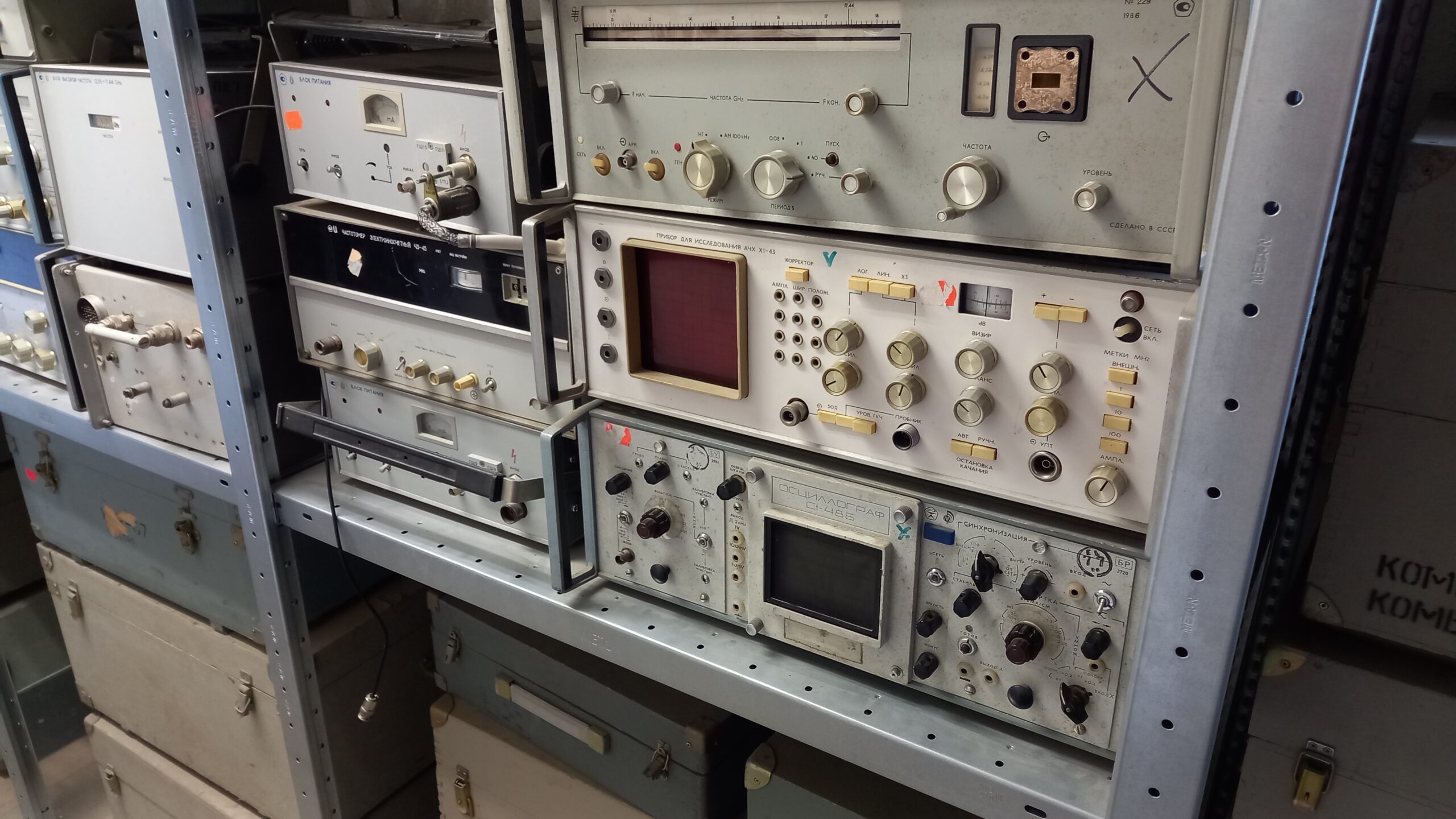
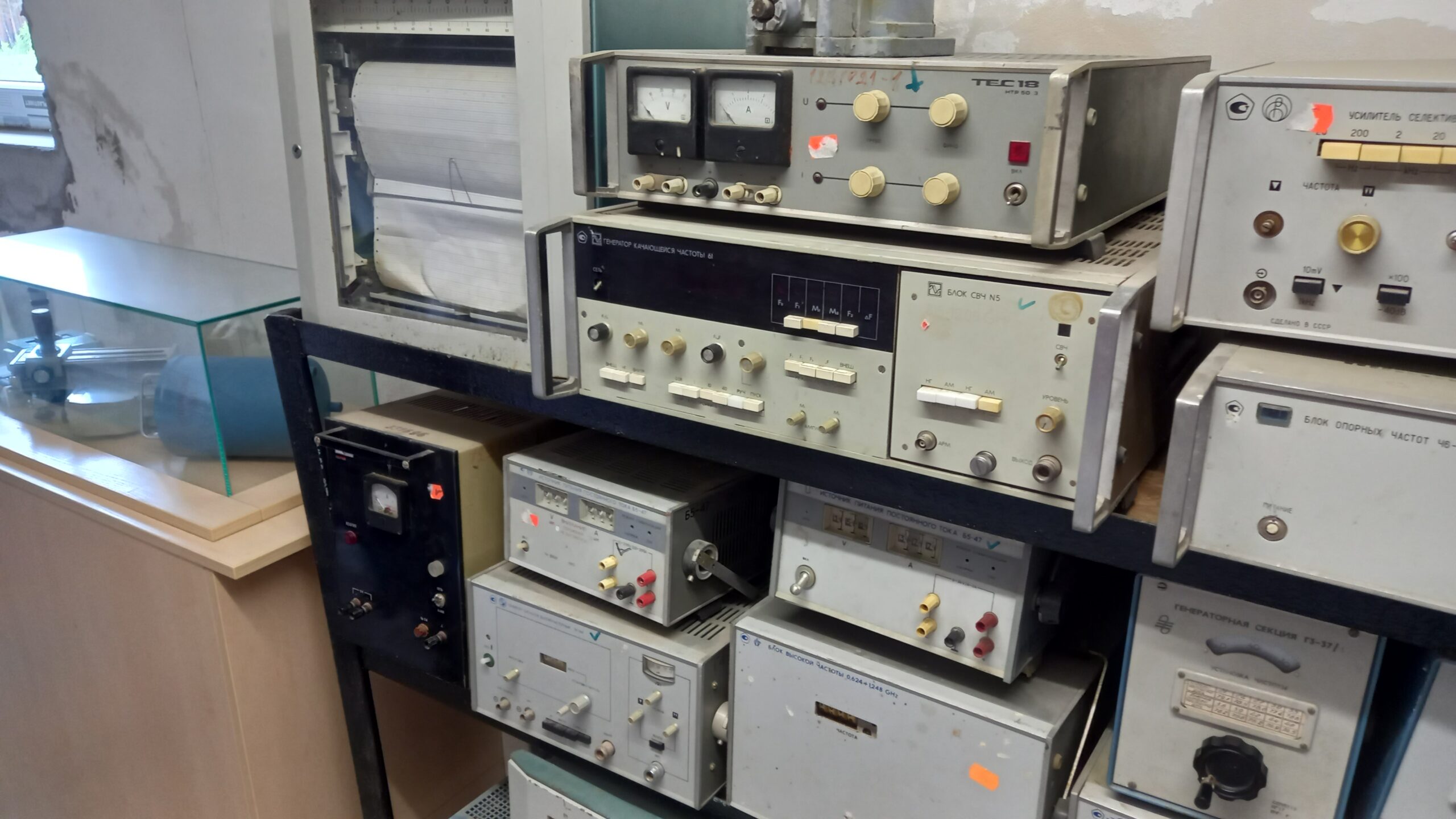
An antenna tracking console, laid out perfectly symmetrically for the two axes of a parabolic antenna: left half: АЗИМУТ = azimuth (horizontal angle/rotation about the vertical axis); right half: УГОЛ МЕСТА = elevation angle (angle above the horizon). Both sides are identically built – typical for a two-axis antenna control console: СКОРОСТЬ МЕДЛЕННО / БЫСТРО, ТОК ЭМУ-Д / Г-Д = „speed slow/fast, current EMU-D / G-D“ (EMU = rotary converter, G-D = generator-motor drive, i.e. a Ward-Leonard drive system – the standard for the heavy antenna motors of such large antennas).Close-up. Tracking console of the satellite antenna in Irbene. Lying next to it is a decree of the Government of the Republic of Latvia dated 19 July 1994, by which the former Soviet military installation was officially transferred to the Ventspils International Radio Astronomy Centre. This marked the beginning of the conversion of the secret facility into a civilian research institution.Portable remote-control and display unit for antenna positioning, presumably part of the control chain of one of the Irbene parabolic antennas (RT-16 or RT-32). Two identical modules for АЗИМУТ (azimuth) and УГОЛ МЕСТА (elevation): each with a СКОРОСТЬ needle instrument for indicating the rotational speed of the drive motors, plus two mechanical angle counters per axis – ПО (грубый отсчёт, coarse reading, 1 scale division = 0.5°) and ТО/ТС (точный отсчёт, fine reading, 1 scale division = 20 arc-seconds) for precise position determination. The green pilot lamp РАБОТА РАЗРЕШЕНА („operation permitted“) signals clearance to move the antenna; the two chrome-plated hand wheels at the bottom are for manual tracking. The carrying handle on top makes clear that this unit was designed as a portable secondary display – for example directly at the antenna base or for a second control post – supplementing the stationary main control console.Opened antenna control console with a view into the electromechanical switching logic: an older version of the two-axis control for azimuth (АЗИМУТ) and elevation (УГОЛ МЕСТА), recognisable by the heavily rated V/A needle instruments (up to 500 V/400 A) for monitoring the voltage and current of the drive motors – clearly rated more powerfully than in more compact later models. The ГО/ПО/ТО counters provide coarse, medium and fine angle readings; the key panels above switch aggregates (АГРЕГАТ), supply voltages (=220V/=24V), operating modes (БЫСТРО/МЕДЛЕННО), and safety functions such as maximum-relay reset (ВОЗВРАТ МАКС РЕЛЕ) and the alarm siren (СИРЕНА). Through the open hatch in the middle of the console, the underlying cam-switch and relay technology becomes visible – wiper contacts, couplings and wiring which, before the era of integrated control electronics, formed the actual „logic“ for limit shut-off, travel limiting and mode switching of the antenna. The stamped codes („В-06-08“ and similar) are presumably assembly or manufacturing identifiers. A vivid example of the transition from purely electromechanical to later semiconductor-based antenna control of Soviet design.Historic receiving equipment of the Irbene satellite station. The display case shows devices from the operational period of the former Soviet facility, including tape recorders, measurement and radio equipment, as well as transport containers for liquid nitrogen. This cryogenic coolant was used to cool the especially sensitive microwave receivers to around −196 °C, which greatly reduced their own noise and allowed even extremely weak signals from space to be received.More old measuring equipmentEven more measuring equipmentThis looks like a classic Soviet measurement setup for noise-figure measurements, of the kind needed at a radio astronomy station like Irbene to calibrate the sensitivity of receivers/amplifiers. Here is a translation of the labels: Top right: ВОЛЬТМЕТР УНИВЕРСАЛЬНЫЙ В7-26 = „Universal voltmeter V7-26“, built in 1984. This is a widely used Soviet digital/analogue multimeter for voltage, current and resistance – a standard lab instrument, comparable to a good Fluke multimeter of the era. Bottom right: ГЕНЕРАТОР ШУМА Г2-32 = „Noise generator G2-32“, built in 1981. It serves as a source of a calibrated noise signal in the HF range. The scale shows kT₀ (noise temperature relative to the reference temperature T₀=293K) – presumably used at Irbene to measure the noise figure of the receiving amplifiers. The labels: СПЕКТРАЛЬНАЯ ПЛОТНОСТЬ ШУМА = spectral noise density; ЧАСТОТА / ТОК ДЕТЕКТОРА = frequency / detector current; РОД РАБОТЫ with ГШ ВКЛ/ВЫКЛ = operating mode, „noise generator on/off“; ВНЕШН МОД / ВНУТР МОД = external/internal modulation; ВЫХОД ПРИЕМН, ВЫХОД СИНХР = receiver output, sync output. Left, the two grey units: БЛОК УПРАВЛЕНИЯ = „control unit“ (upper unit) – with controls for МОДУЛ (modulation), ГЕТ (heterodyne/oscillator), ПОДСТРОЙКА (fine tuning), ЧАСТОТА (frequency), ДИОД, КОМПЕНСАЦИЯ. Presumably controls a sweep generator/klystron section. БЛОК ИНДИКАЦИИ = „display unit“ (lower unit) – with a digital „×10“ display for GHz/dB, controls for ОСЛАБЛЕНИЕ dB (attenuation), РОД РАБОТЫ, КАЛИБРОВКА (calibration). Together, the control and display units presumably form a noise-figure meter (измеритель коэффициента шума) – the display unit evaluates the noise signal fed in from the G2-32 and shows the noise figure or gain of the device under test in dB. The small black box at the top with the coloured buttons could be a simple auxiliary control panel or a power supply/switching module – unfortunately no legible label can be made out in the photo.Here a quite different class of equipment: time measurement/frequency standards and frequency-response analysers. Translation from top to bottom: Top: СИНХРОНОМЕТР КВАРЦЕВЫЙ Ч7-15 = „Quartz synchronometer Ch7-15“. This is a high-precision quartz time/frequency reference with a counter. Labels: УСТАНОВКА ВРЕМЕНИ = time setting; РЕЖИМ РАБОТЫ / КОРР. ШК. ВР / СИНХР ИМПУЛЬС = operating mode / time-scale correction / sync pulse; ЗАДЕРЖКА = delay (the counter at top right shows a delay time); КОРРЕКЦИЯ КВАРЦА = quartz correction; ШК.ВР II / ШК.ВР III / МАРКЕР (outputs) = time-scale outputs II/III, marker. Such devices provided a very precise, quartz-stabilised time/frequency base for the station – essential for a radio telescope that requires exact timestamps for its observations. Middle: ПРИБОР ДЛЯ ИССЛЕДОВАНИЯ АЧХ Х1-46 = „Instrument for investigating the amplitude-frequency response (АЧХ = amplitude-frequency characteristic) X1-46“. This is essentially a sweep test set / network analyser with a built-in screen (the reddish tube on the left) – used to directly view the frequency response of a device under test as a curve. Controls: ОСЛАБЛЕНИЕ (attenuation), КОММУТ (switching), ОТСЧЕТ (readout), ЛОГ dB (logarithmic dB scale), ПОСТОЯННАЯ ВРЕМЕНИ (time constant). Bottom: ПРИБОР ДЛЯ ИССЛЕДОВАНИЯ АЧХ Х1-48 = same principle, identical equipment series X1-48 – likewise a frequency-response/sweep instrument, with its own display tube, controls for ЧАСТОТА (frequency), ПОЛОСА (bandwidth), ПЕРЕКЛ (switching). Bottom right: МИЛЛИВОЛЬТМЕТР ЦИФРОВОЙ В3-52/I = „Digital millivoltmeter V3-52/I“ – a precision AF/HF millivoltmeter with measuring ranges from 10 mV to 3000 V (scale at bottom right: 10, 30, 100, 300, 1000, 3000). Altogether, then: a combination of a precise time/frequency reference (top) and two sweep/frequency-response test sets (X1-46, X1-48) plus a precision millivoltmeter – typical instrumentation for measuring and calibrating the receiver and amplifier chains of a radio astronomy station like Irbene.Top right: ГЕНЕРАТОР СИГНАЛОВ СПЕЦИАЛЬНОЙ ФОРМЫ Г6-28 = „Special-waveform signal generator G6-28“. A function generator that produces various signal shapes – recognisable from the symbols for НГ (sawtooth), square, triangle, etc. Labels: ЧАСТОТА Hz = frequency Hz, with МНОЖИТЕЛЬ (multiplier, 10⁻³ to 10⁵); ФАЗА = phase (0°/−/+); ВНЕШНИЙ ЗАПУСК = external trigger; АМПЛИТУДА / СМЕЩ. СИГН. = amplitude / signal offset; 50Ω / 600Ω output impedance, dB scale; СДЕЛАНО В СССР = „Made in the USSR“. Below: ИЗМЕРИТЕЛЬ РАЗНОСТИ ФАЗ ФК2-12 = „Phase-difference meter FK2-12“. A precision instrument for measuring the phase difference between two signals (channel A/B) – exactly what is needed at a radio telescope with multiple antennas/receiving channels (interferometry!). Details: ЗАХВАТ ЧАСТОТЫ = frequency lock; ДИАПАЗОН ЧАСТОТ MHz = frequency range in MHz (scale 100–1000); left needle instrument: ШКАЛА mV, 200 µA, dB scale; right needle instrument: phase angle φ° with ШКАЛА φ° ±6/±18/±60/±180; СДВИГ ШКАЛЫ = scale offset; КАНАЛ A/B = channel A/B; ВНИМАНИЕ! ПРОБНИКИ ПЕРЕД ВКЛЮЧЕНИЕМ ПРИБОРА… = „Caution! Do not expose the probes to static charge / ground them before switching the instrument on“ (ESD-protection warning); ФАЗА ГРУБО = phase, coarse setting. Left (partially visible): a unit with ПОСТОЯН. ВРЕМЕНИ (time constant, 0.1/0.3/1/3/10) – presumably an amplifier or filter add-on, nameplate not legible. Bottom left: БЛОК ВЫСОКОЙ ЧАСТОТЫ = „high-frequency module“, with a GHz display – presumably part of an HF generator or receiver, the rest of the label outside the frame.R4-11 – complex transmission-coefficient measuring set (vector network analyser), built in 1983, serial number 17102: a Soviet precision instrument for measuring the magnitude and phase of a transmission coefficient – it simultaneously measures attenuation/gain (МОДУЛЬ dB, switchable ±10/20/30/40 dB, logarithmic) and phase shift (ФАЗА, ±2.7°/±27°/±270°) of a device under test, optionally in polar or Cartesian display (ПОЛЯРН/ДЕКАРТОВАЯ). Built-in small graticule screen for direct display, with controls for calibration (КАЛИБР.), phase balancing (ВЫРАВНИВАНИЕ ФАЗЫ) and fine adjustment of the reading (ПЛАВНО УСТ.). Connected above it is the associated reference-frequency module „Блок опорных частот Ч6-31“ with supply voltages of +12.6 V / −6.3 V / +27 V and a 1 MHz reference output – providing the stable time/frequency reference such vector measurements need for correct phase evaluation.MkII-C VLBI Data Formatter, manufactured by the Australia Telescope National Facility (CSIRO): a timestamping and formatting unit for Very Long Baseline Interferometry – it tags the incoming intermediate-frequency signal (IF INPUT) with a high-precision time code (DAY NUMBER, TIME UT in HH/MM/SS) and the deviation from the reference clock (CLOCK DIFFERENCE), so that the recording can later be correlated exactly with data from other, distant radio telescopes. With synchronisation logic (STATUS SYNC/ARM, SET/RUN/RESET), test-pattern generator (TEST PATTERN START/STOP), PLL lock indicator (LOCK PLL), and its own calibration source (CAL SOURCE) with selectable reference frequencies (1PPS, 5 MHz, etc.). The markings „3“ / „I1“ suggest a channel in a multi-channel VLBI recording system – an example of the Western timing and digital technology with which the facility was upgraded for international radio astronomy after 1994.Rack of measuring equipment with HF sweep test technology, built in 1986: at the top, a GHz sweep generator (СДЕЛАНО В СССР, frequency range adjustable via FНАЧ./FКОН. with a scale up to 17.44 GHz, modulation НГ/AM 100 kHz) with a built-in milliammeter and a waveguide flange connector (the square copper fitting on the right) for the signal output in the centimetre-wave range. Below it, the frequency-response analyser „Прибор для исследования АЧХ Х1-43“ with its own display tube for direct curve display (АМПЛ./ШИР./ПОЛОЖ. for amplitude, width, position; ЛОГ./ЛИН. for logarithmic/linear display; МЕТКИ МГц for 1/10/100 MHz frequency markers). To the left, two further modules: a power supply (Блок питания) with an anode-voltage output for tube circuits, plus an electronic counter/frequency meter Ч3-45. At the very bottom, the oscilloscope С1-48Б, a widely used two-channel Soviet general-purpose oscilloscope with the classic controls for time base (РАЗВЁРТКА), sensitivity (ЧУВСТВИТЕЛЬНОСТЬ, V/cm), triggering (СИНХРОНИЗАЦИЯ internal/external) and X/Y operation – the workhorse of every Soviet electronics workshop, used here to check the sweep curves from the equipment above.Rack of measuring equipment in an outbuilding at Irbene: sweep generator „Генератор качающейся частоты 61“ with HF extension „Блок СВЧ №5“, above it a two-channel bench power supply (model TEC 18, presumably of Bulgarian manufacture) and a strip-chart recorder for logging signal levels. Below that, two precision DC sources Б5-47 as well as an HF module for the 0.624–1.248 GHz range – typical equipment for calibrating and maintaining the radio telescope’s receiving chains, mostly of Soviet manufacture from the 1970s/80s.
In brief: Irbene was officially the „Станция космической разведки «Звезда»“ (Space Reconnaissance Station „Zvezda“), Military Unit 51429, more precisely the „649th Independent Reconnaissance Post for Radio Emissions from Space Objects, Ventspils“. The name already says a great deal: the main task was not the interception of terrestrial microwave-relay links, but the reconnaissance of signals from space – that is, satellites.
What exactly was intercepted?
Signals from Western/NATO military and communications satellites – downlinks from reconnaissance, communications and navigation satellites
Telemetry from rocket tests and spacecraft – whenever the US or NATO states tested rockets or satellites, their telemetry data could be intercepted as they flew over the North Atlantic/Europe
Satellite tracking itself (space surveillance) – where a given satellite is located, what its orbital parameters are
Why from precisely there, and with such large dishes? This is the crucial technical point: a terrestrial microwave relay link (a point-to-point link, e.g. between two hill stations in West Germany) transmits in an extremely tight beam along the line of sight between the two antennas. To intercept such a link you have to sit in or near the beam itself – which the Soviets indeed did, but by other means: mobile interception units, listening posts near the border, or by picking up side lobes close to the link.
From the Baltic states, hundreds of kilometres away, it would be impossible to receive a West German microwave-relay tower – the curvature of the Earth and the tight beam of the signal make that geometrically impossible. A satellite, by contrast, radiates its signal (downlink) across a broad „footprint“ covering a huge area of the Earth, often thousands of kilometres in diameter – which is exactly what a large, highly sensitive parabolic antenna like the RT-32 is built for: it picks up the already widely spread but very weak signal at the edge of the footprint.
Frequency ranges: Typical for this type of space/satellite reconnaissance were
VHF/UHF (approx. 100–400 MHz) for older telemetry and some military satellites
L-band (1–2 GHz) for navigation and some communications satellites
C-band (4–8 GHz) and partly X-/Ku-band for satellite communications and reconnaissance-satellite downlinks
Incidentally, this fits well with one of the devices shown here: the „Блок высокой частоты 0.624–1.248 GHz“ falls exactly within this range, typical for satellite reception.
On decoding: It is publicly documented that such stations worked with demodulating receivers, which first mixed the received HF signal down to an intermediate frequency (hence the many „Блок СВЧ“ units, sweep generators and frequency converters), then demodulated it (AM/FM/PCM depending on the satellite type), and finally recorded it on tape or punched tape for later analysis by signals-intelligence and cryptanalysis units in Moscow. For obvious reasons there is hardly any solid, declassified information available on the actual decryption of individual NATO satellite systems – that remains, for the most part, buried in the respective intelligence archives to this day.
Standing on the antenna: The highlight: we were actually allowed to stand on one of the parabolic antennas – a feeling you don’t forget quickly, once you consider what that dish was once used for.
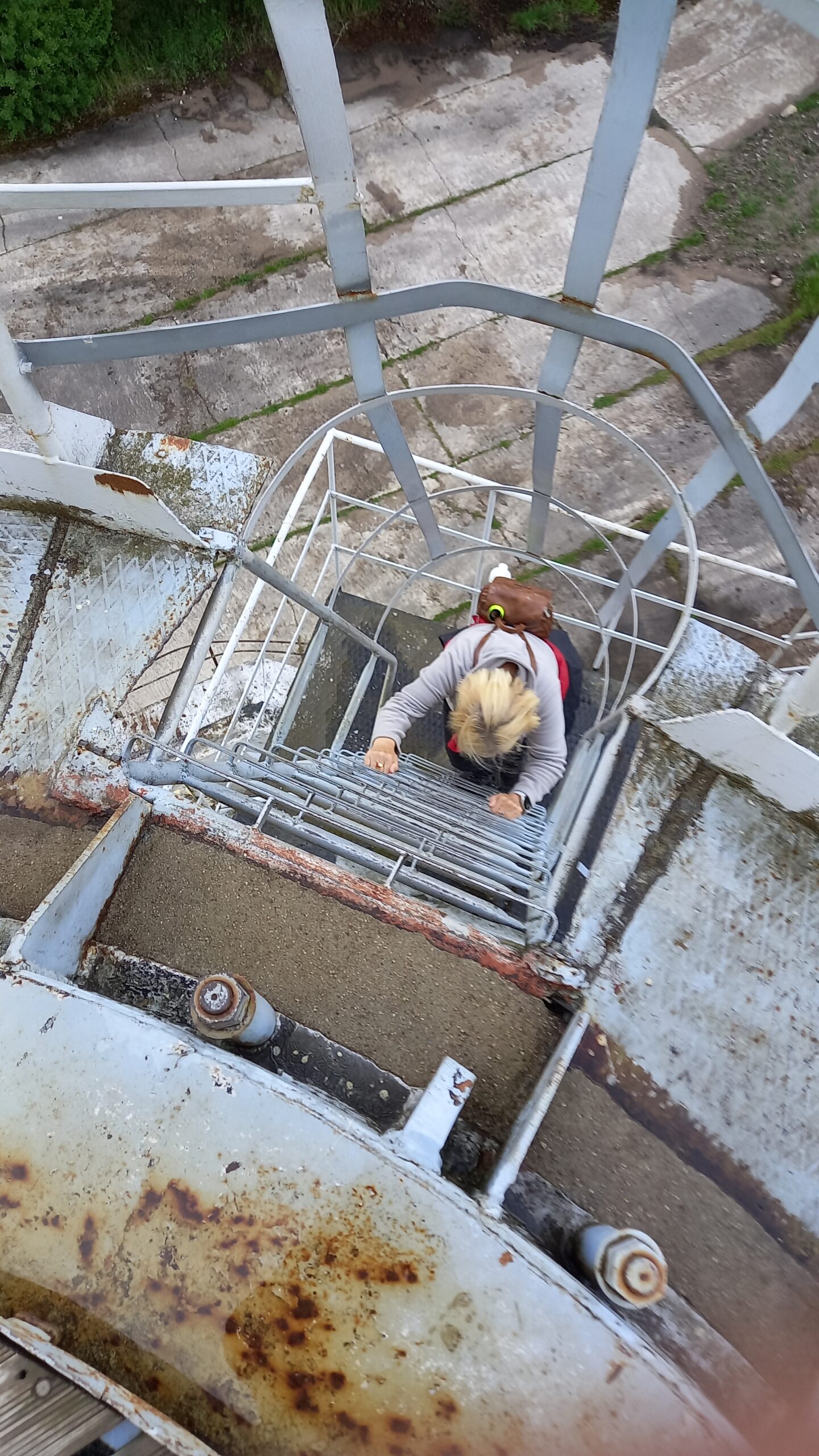
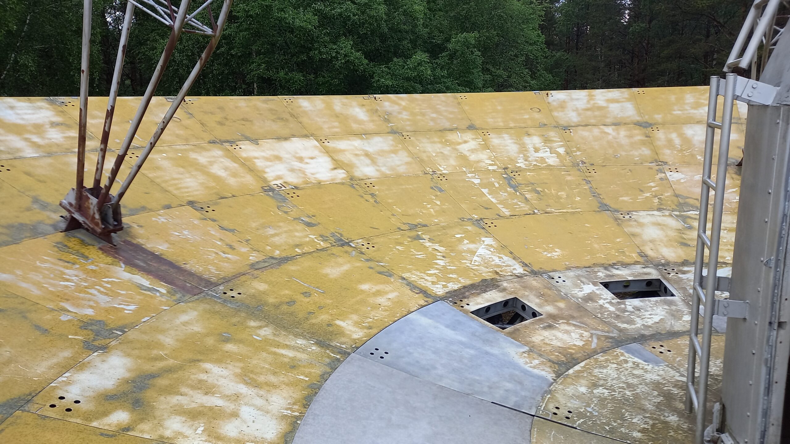
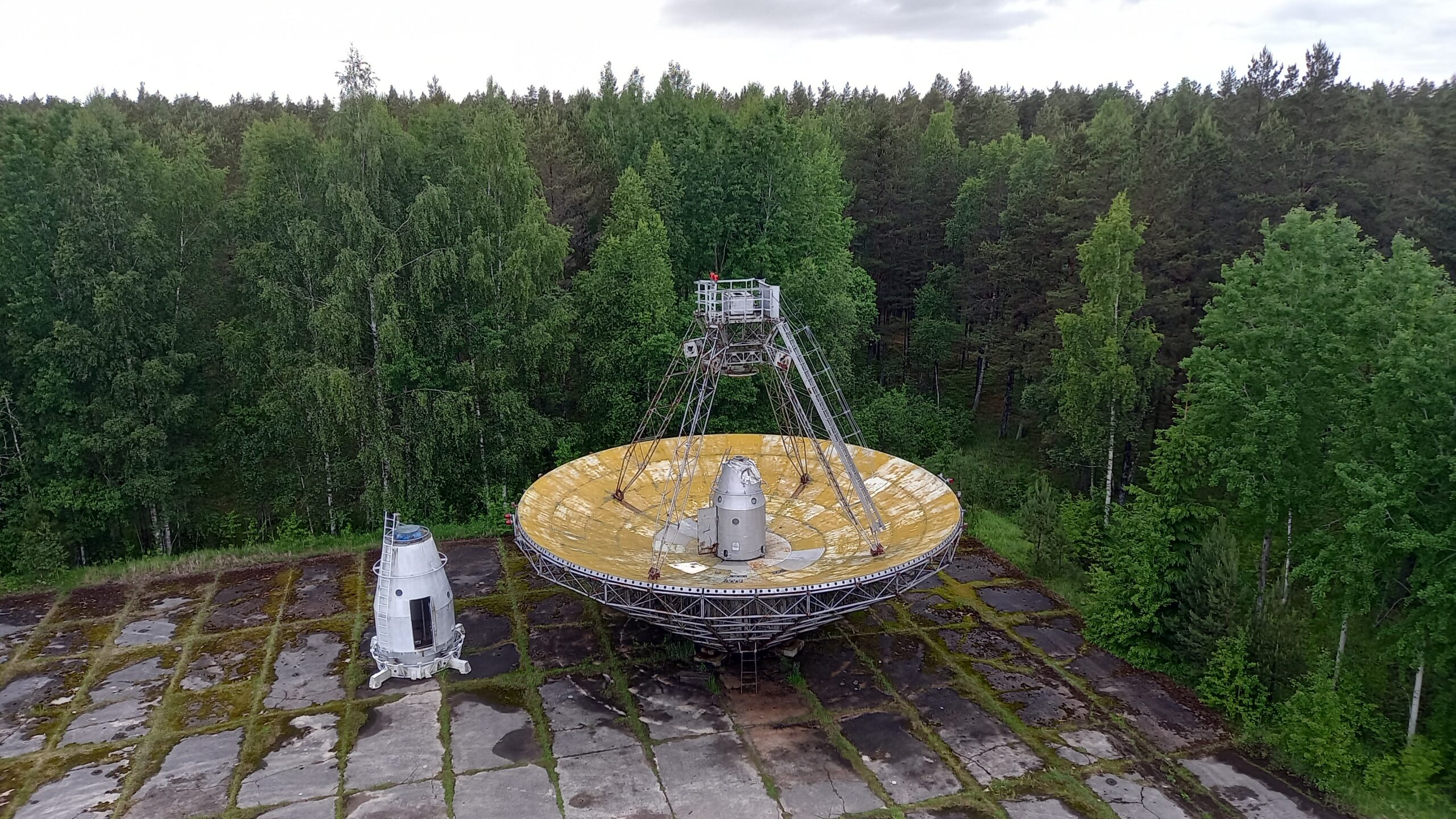
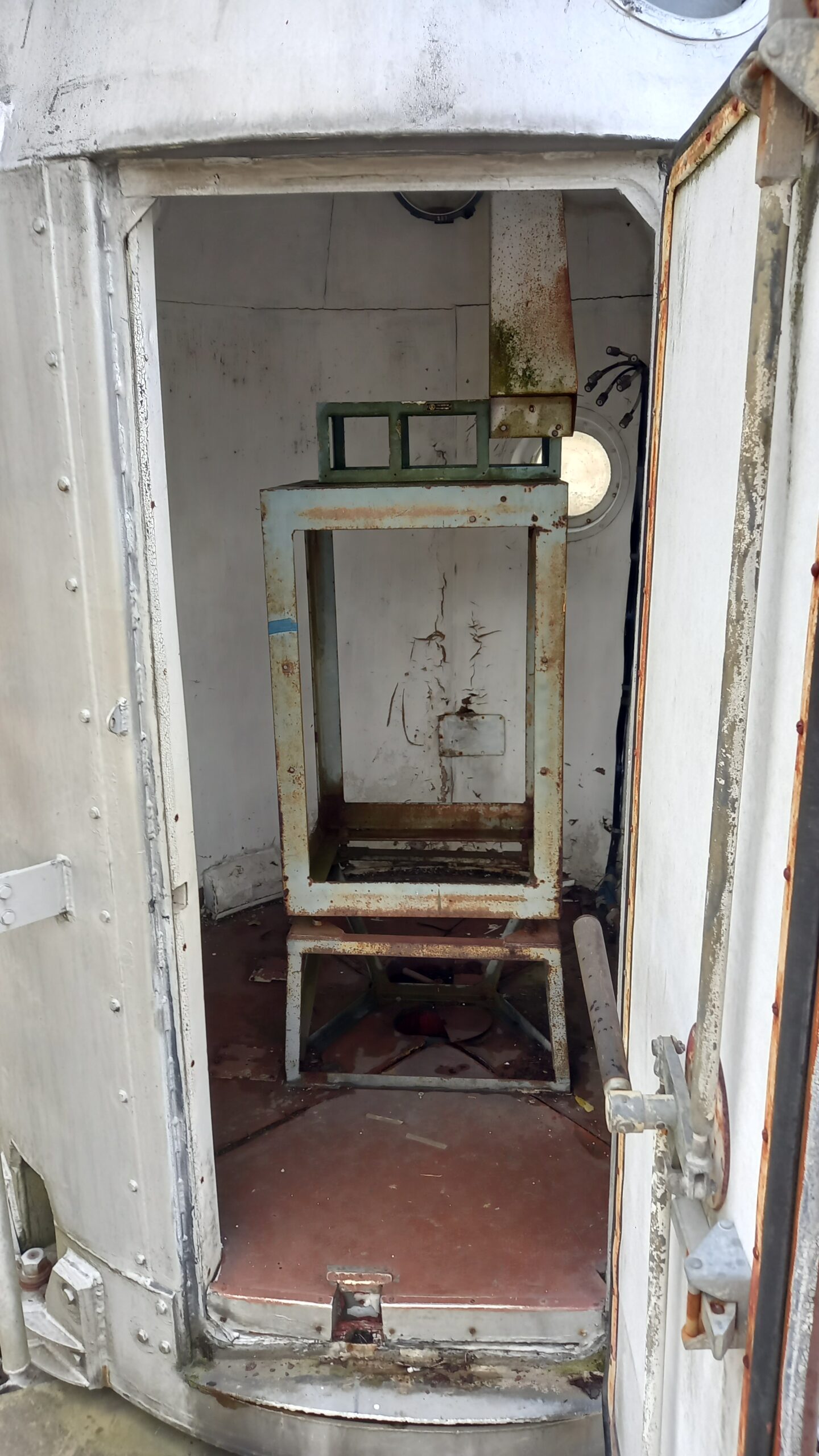
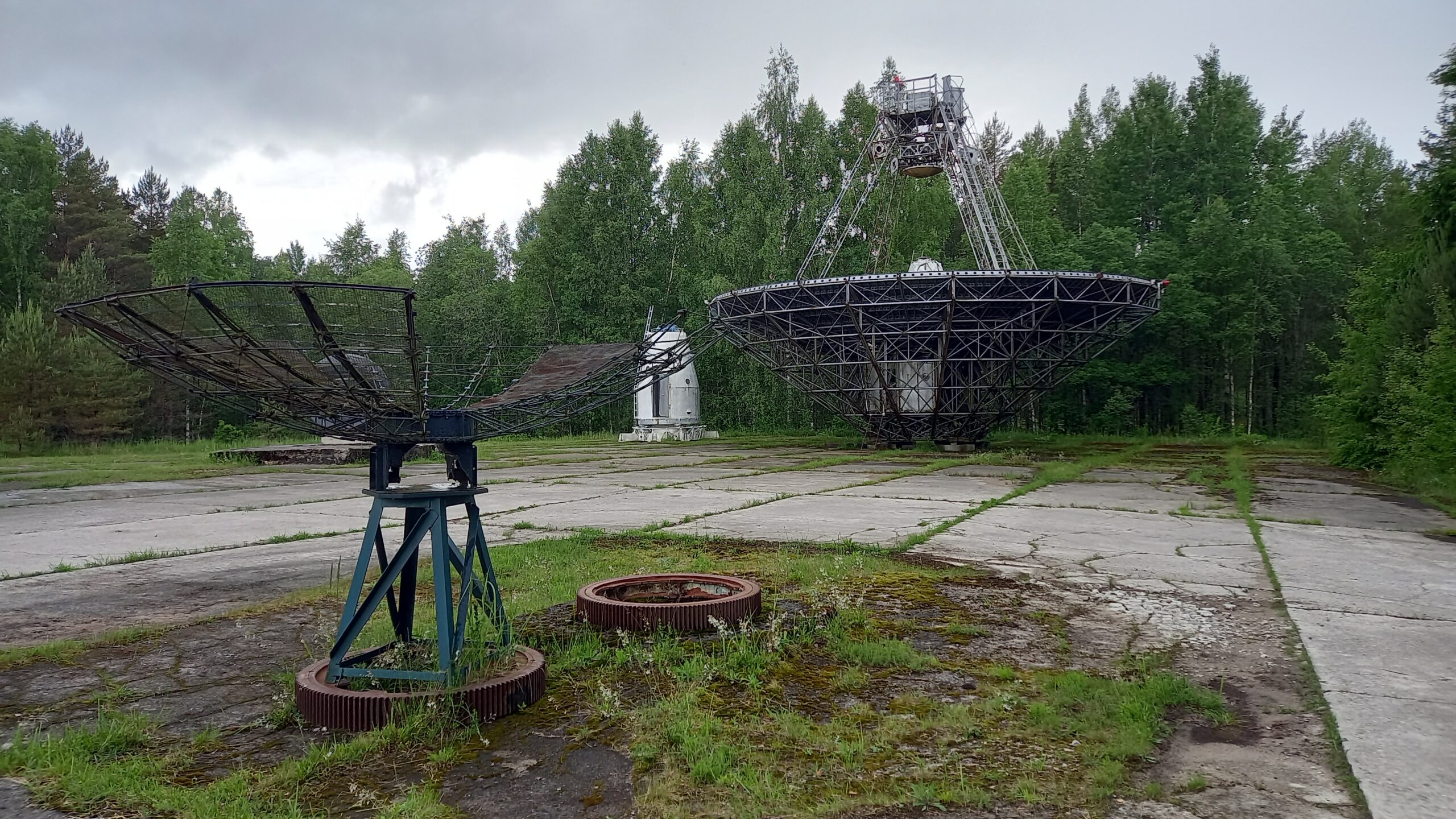
Climbing up to the RT-16 parabolic antennaThe RT-16. A unique experience, being allowed to stand on a parabolic antenna.This is the RT-16 – the smaller of the two surviving Irbene antennas, with a 16-metre dish diameter (half the size of its big sister, the RT-32). The RT-16 sits on a much lower, flat mounting platform rather than a tall, slender tower – which means the dish can be climbed directly from the concrete foundation via the side ladders, and visitors can actually stand on the reflector surface itself. It is exactly this accessibility that makes it a popular photo spot and highlight of the tours – with the RT-32 this would be practically impossible, given its height and the weight of the structure.The receiver has long since been removed.
Receiver technology at Irbene: The massive antenna installations at Irbene required extremely sensitive receiving systems in order to pick up the very weak signals from satellites and spacecraft at great distances. Cooling of the high-frequency preamplifiers played a crucial role here. The Dewar flasks shown in the exhibition presumably served to store and transport liquid nitrogen, with which the sensitive input stages of the receivers were cooled to around −196 °C. By reducing thermal noise, the sensitivity of the system could be greatly increased.
In the early phase of microwave technology, such installations used cooled parametric amplifiers. For particularly demanding applications, maser receivers were also used, which were among the most sensitive microwave amplifiers of their time. These, however, required elaborate cooling with liquid helium and were more specialised devices. Later, low-noise semiconductor amplifiers based on GaAs and HEMT technology replaced the older systems.
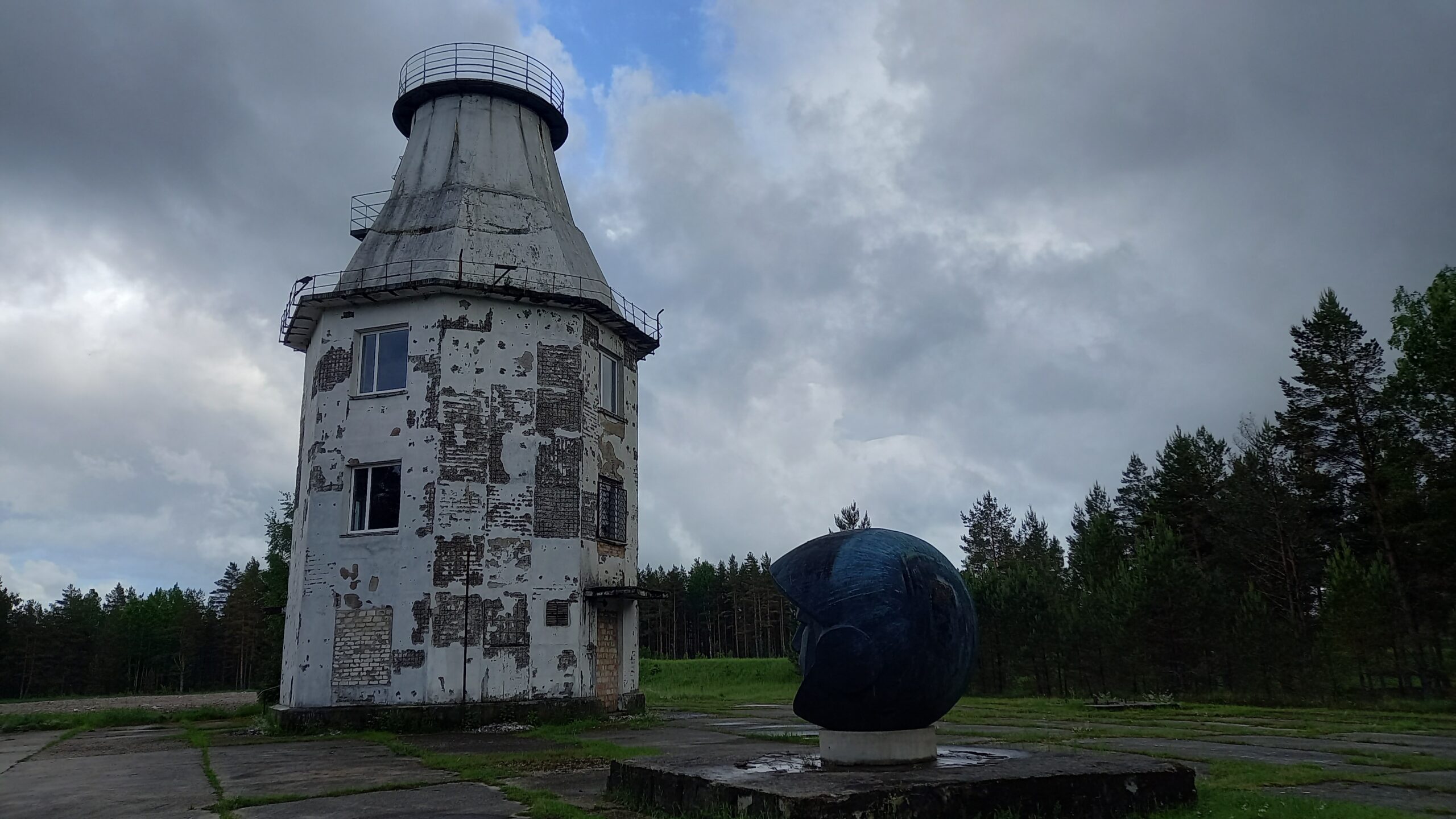
The RT-16 can be seen in the background. In the foreground, a parabolic antenna that was found in a lake.The tower of the RT-8, Irbene: originally the mount for the smallest of the three Soviet radio-telescope antennas, which was completely dismantled after the troop withdrawal in 1994. The characteristic concrete tower, tapering upward with a surrounding observation platform, was preserved and today houses an exhibition on the history and function of the RT-32 and RT-16 during the Soviet period. The weather-beaten facade, in places stripped down to the bare brick, tells its own, uncommented story of decay and reconstruction. The dark head sculpture in the foreground forms a deliberately placed artistic counterpoint to the site’s sober military architecture.
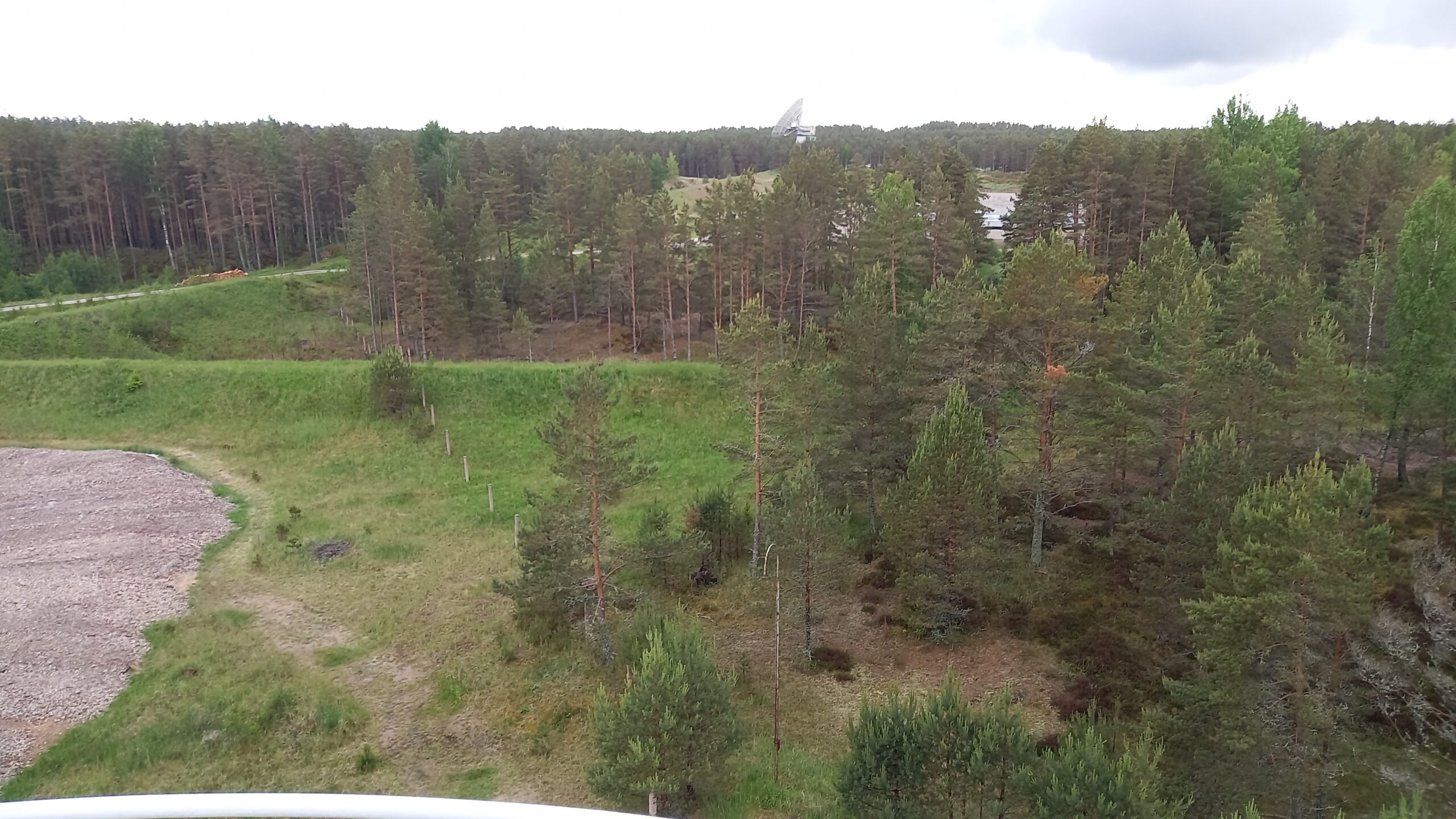
600 metres through the cable tunnel: Afterwards we walked along an underground tunnel roughly 600 metres long, which once served as a cable duct and leads to the largest antenna – the RT-32, over 30 metres in diameter, now used for space research. You need a torch, or at least the LED light on a smartphone, to walk it.
Explanation: An underground cable tunnel runs between the two surviving radio telescopes, RT-32 and RT-16, officially stated by VIRAC to be 700 metres long. It originally served as a protected, weatherproof cable route between the two antenna sites.
Original purpose (Soviet era): In a classic cable tunnel of this type („кабельный туннель“), several kinds of lines typically ran in parallel:
Coaxial cables for the HF intermediate-frequency signals between the antennas and the central evaluation electronics
in some cases waveguides for higher frequency ranges, where coaxial cable would have been too lossy
Control and power-supply cables for the antenna drives
presumably synchronisation or time-signal lines, so that both antennas could operate phase-locked for interferometry measurements
Current use: The original, massive cable infrastructure has been decommissioned or removed. Instead, a fibre-optic cable now provides data transmission between RT-32 and RT-16 – important for operation as an interferometer, for instance when observing methanol masers in star-forming regions, for which both antennas must combine their raw data in time and phase synchronisation. In addition, a telephone line serves as a redundant emergency connection.
Structural context: In Soviet terminology this is a classic „кабельный туннель“ – a walkable, enclosed passage with cable trays or brackets along the walls, designed to allow free passage along its entire length so that cables could be laid, inspected and repaired at any time. It was designed from the outset for maintenance staff, not merely as a cable duct, and is therefore still walkable and open for tours today.
Little freely accessible information exists on the exact original technical documentation (cable types, frequency ranges of the original connection), since the Soviet documentation was deliberately destroyed during the withdrawal in 1994.
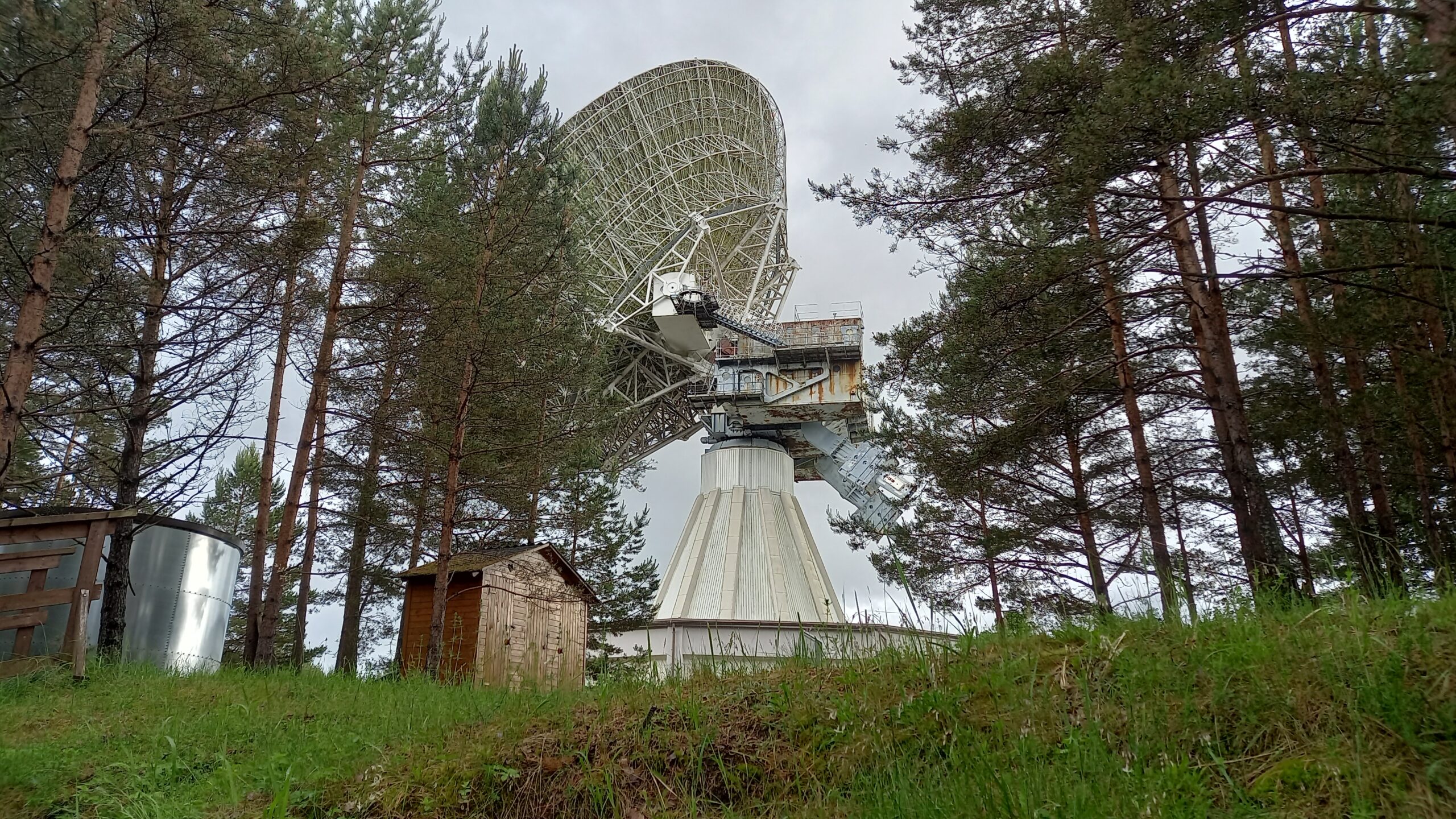
Beneath the earth bank lies the 600-metre cable duct, which can only be walked with a torch.The RT-32, now used for radio astronomy.The famous RT-32, the heart of Irbene. From below the thing really looks monstrous: 32 metres in diameter, over 20,000 components, the central cone alone weighs 80 tonnes, and the whole structure weighs around 600 tonnes. It was, incidentally, built by a Ukrainian shipyard – hence the shipbuilding-style, almost porthole-like look of the tower with the vertical struts, clearly visible on the base building. A few details: the lattice construction of the dish – such an open lattice structure instead of a solid surface saves enormous weight and wind load, but still works as a reflector at the centimetre wavelengths used here, because the mesh size is much smaller than the wavelength. The secondary-reflector/receiver Cassegrain assembly at the tip of the struts in the middle (the small element pointing down towards the centre of the dish). The rusty, massive counterweight/support block behind the reflector, from which the whole dish hangs in the elevation bearing – precisely the mechanism that was driven from the control consoles (АЗИМУТ/УГОЛ МЕСТА). The ribbed, conical tower below, on which the entire rotating structure for the azimuth movement sits. And below that, the functional white base building, which houses all the control and measurement electronics. A truly impressive piece of Cold War engineering, now serving radio astronomy.
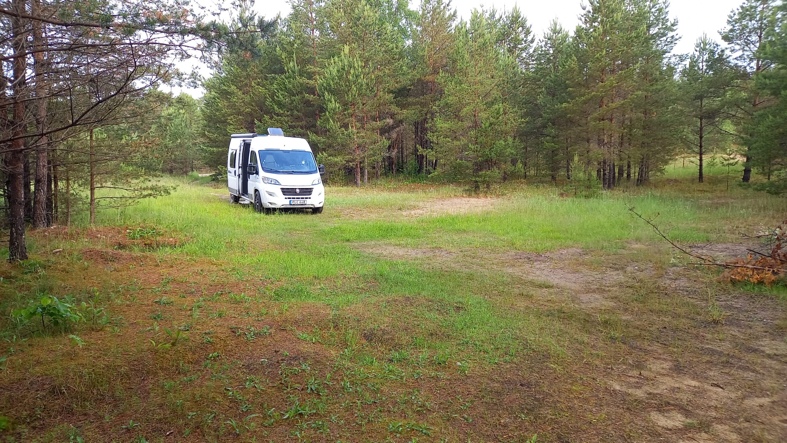
The night after. To end the day, we found a hidden spot to park right in the middle of the lonely forest, directly on the Irbe river. No mobile signal, no way to be reached, nothing – just the forest, the river and the silence. A night completely off the grid, in the middle of the empty forest near Cape Kolka. Almost symbolic after a day full of espionage history: where once every signal was intercepted, suddenly there was none at all.
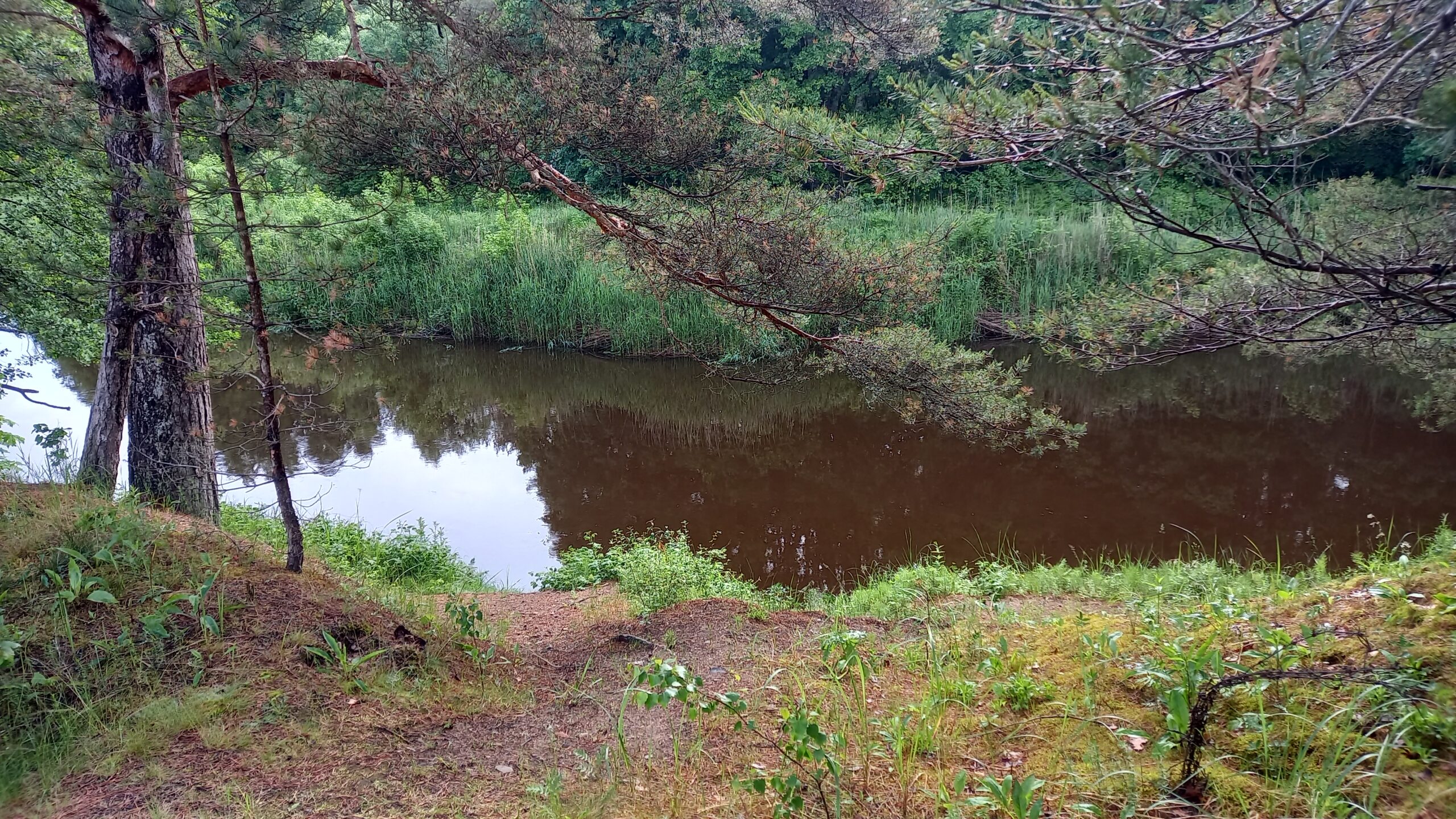
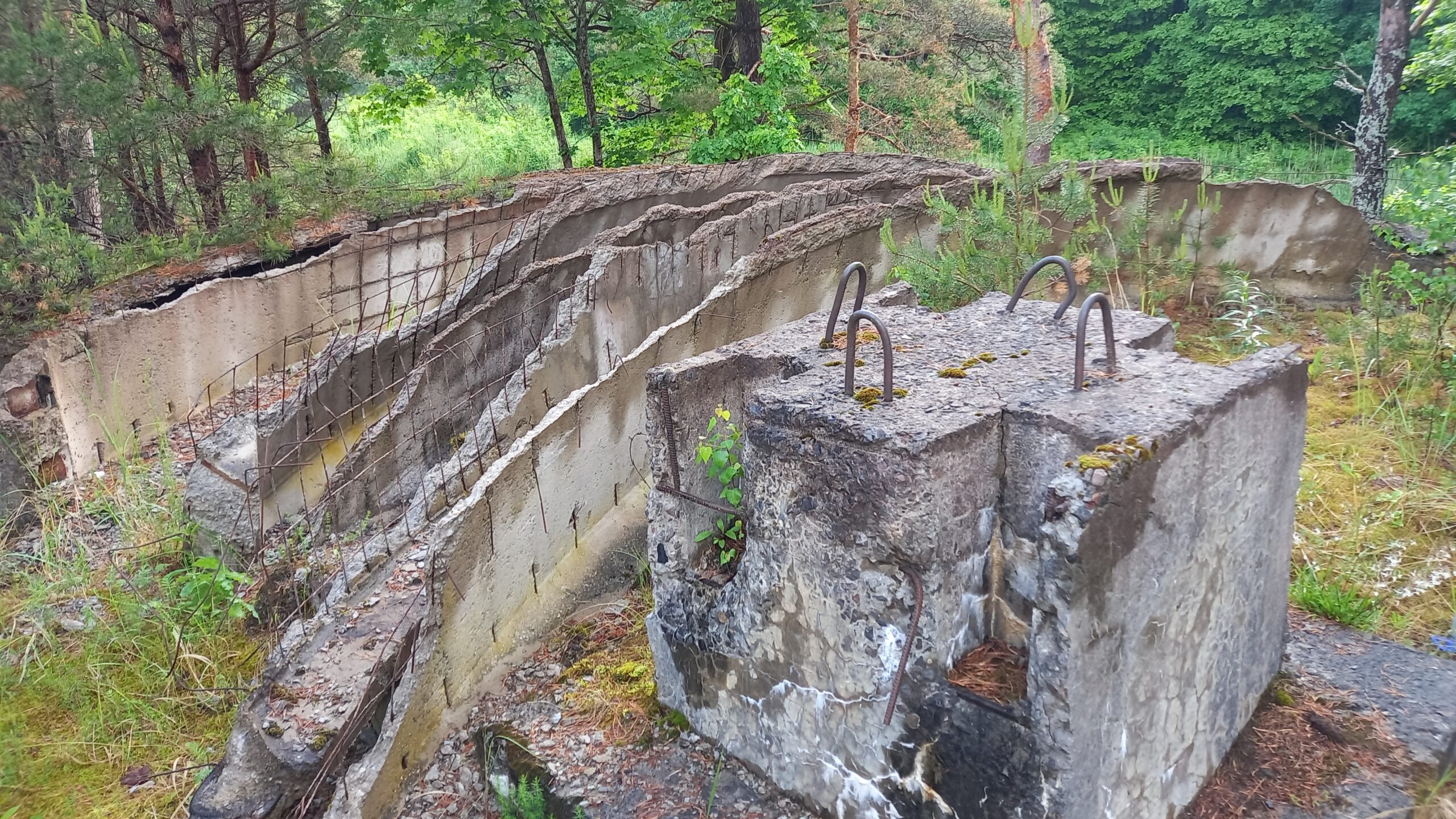
An enchanted clearing near Irbene, deep in the forest. The turn-off was barely visible. Absolutely no mobile signal. Instead, rain and the obligatory mosquitoes.The Irbe river. The name Irbene derives from the nearby Irbe river (Livonian: Īra), which flows into the Gulf of Riga a few kilometres away and also gives its name to the strait between Latvia and the Estonian island of Saaremaa (the „Irbenskii proliv“ / Irbes šaurums). Linguistically, „Irbe“ goes back to a pre-Germanic/Livonian root „ir“ meaning „bog“ – fitting, since the river flows through marsh and bog areas and its water has a brownish, peaty colour. The river, incidentally, held particular significance historically for the local inhabitants, the Livonians, a Finno-Ugric people native to the Baltic region.Concrete remains of an unidentified structure
Who knew about the secret town of Irbene – and why exactly this location? Irbene was so tightly guarded that even within the Soviet Union its existence was known only to a very small circle of people. Access was restricted exclusively to those with special clearance – primarily Soviet Navy personnel, technicians and scientists reporting directly to the central leadership in Moscow. The place appeared on no official map.
Even the political leadership of the Latvian SSR was, according to available reports, not officially informed of the existence and exact purpose of the facility. The Latvian government only gained confirmed knowledge of the full extent of the facility in 1993, during negotiations over the withdrawal of Russian troops following independence.
Choice of location:The choice of the site on the coast at Irbene, near Cape Kolka and the Irbe Strait, can be explained by several factors:
Coastal location on the Baltic Sea: The proximity to the Baltic coast was advantageous for intercepting radio and satellite signals from Western Europe and the NATO area, since it offered an unobstructed line of sight towards the North Sea, Scandinavia and Central Europe, without mountains or larger built-up areas interfering with signal propagation or reception. Peripheral position within Soviet territory: The Kurzeme (Courland) region formed the westernmost part of the Soviet Union on the Baltic, placing it closer to the Western targets under surveillance than comparable sites further inland.
Military tradition of the region: The coast around the Irbe Strait had already been strategically significant since Tsarist times – coastal defence batteries were built here from 1912 onward to secure access to the Gulf of Riga. The area had accordingly been a military restricted zone for decades, with corresponding infrastructure and border surveillance.
Sparse population:The area around Irbene was, and still is, sparsely populated and dominated by extensive forests, which made it easier to build a fully sealed-off, inconspicuous facility and favoured secrecy towards the civilian population.
The facility itself was built from 1967/1971 onward under the codename „Zvaigzne“ („Star“) by the Soviet Navy and assigned to military intelligence.
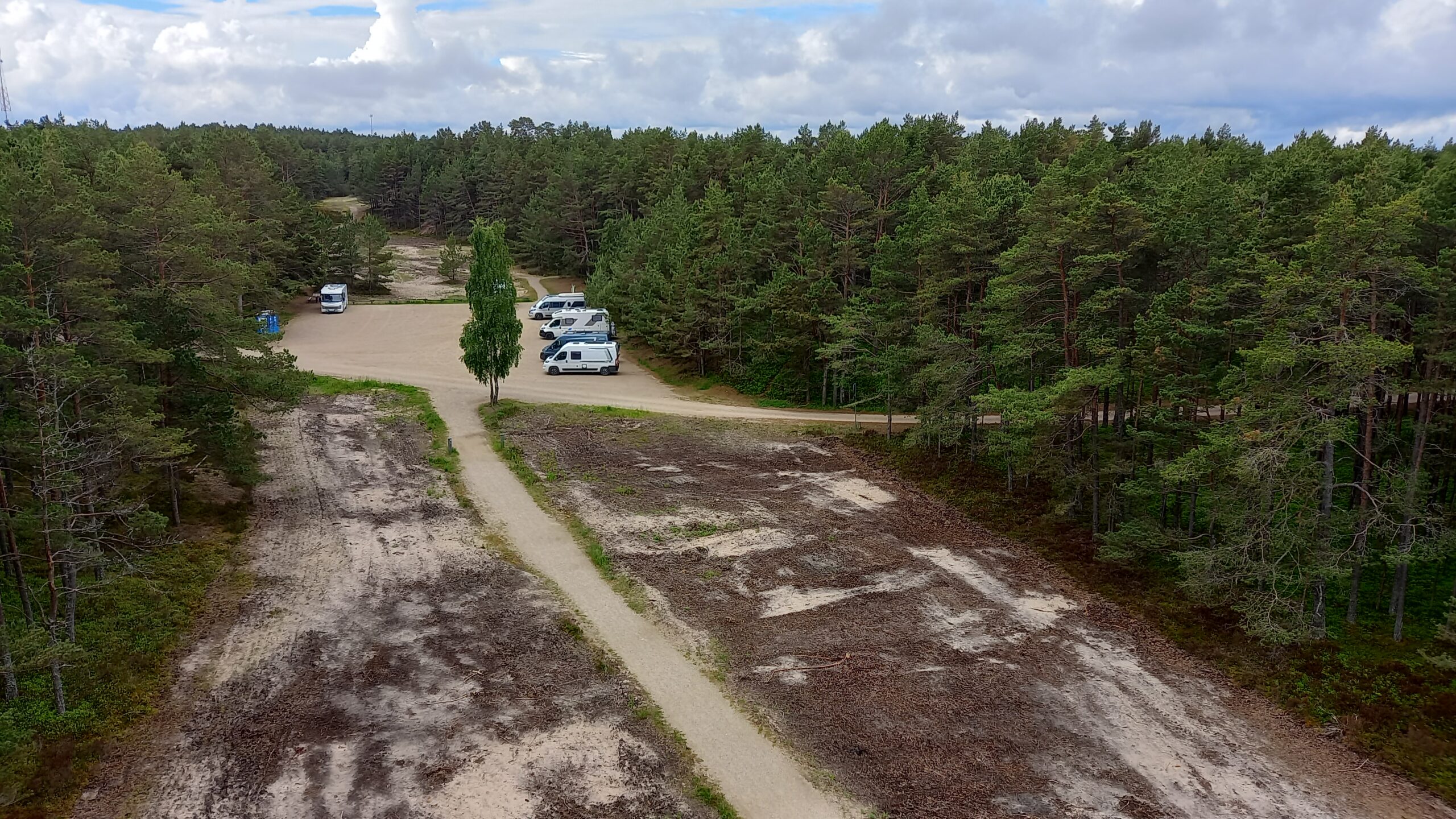
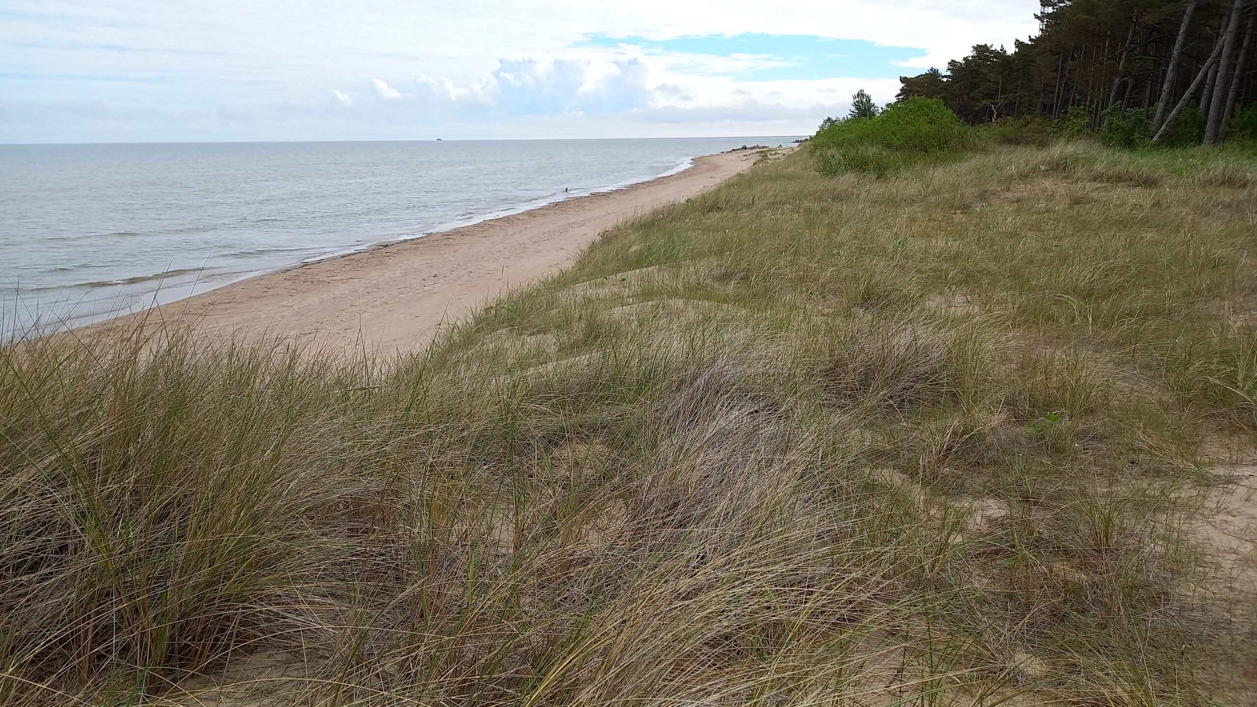
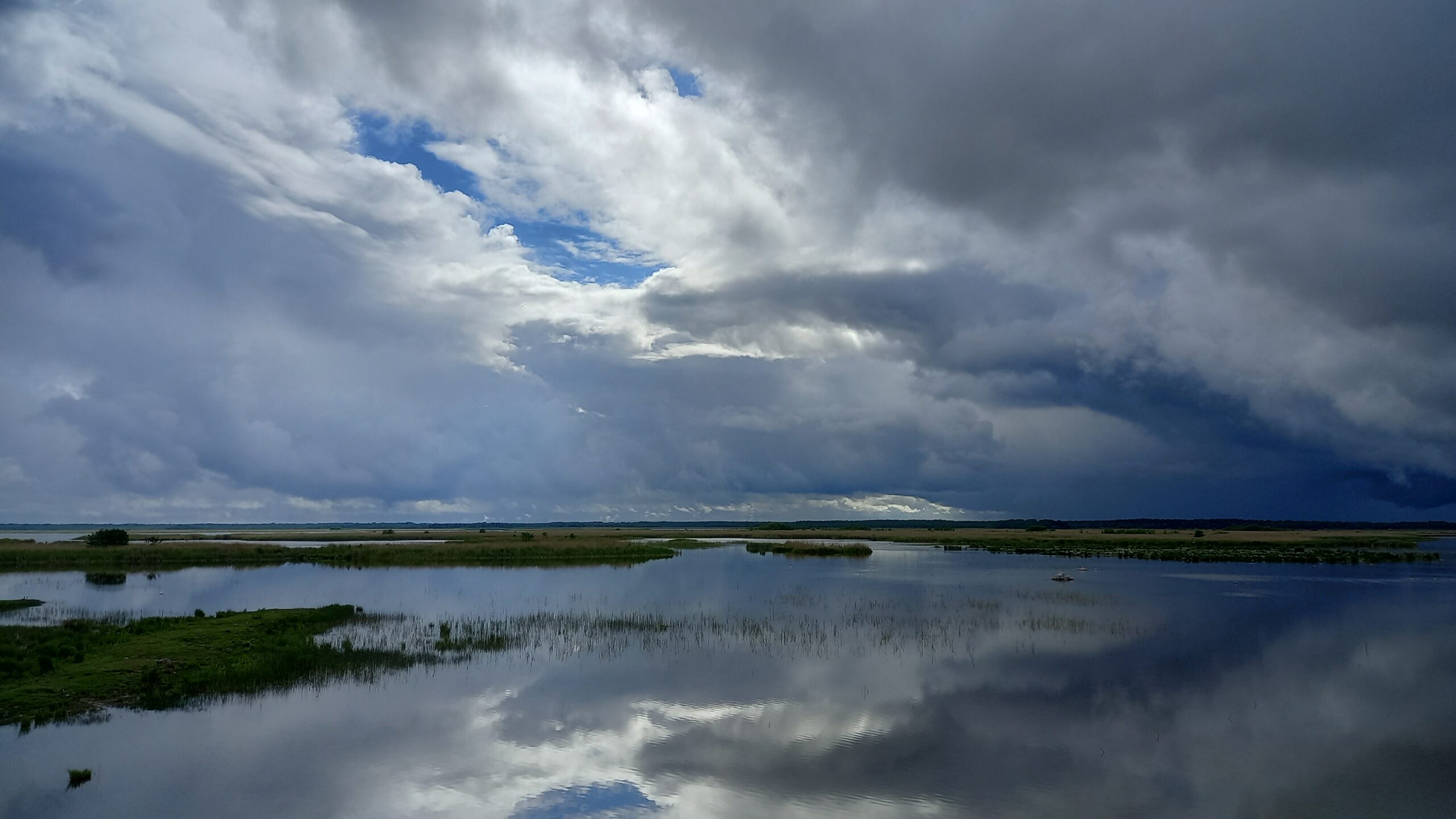
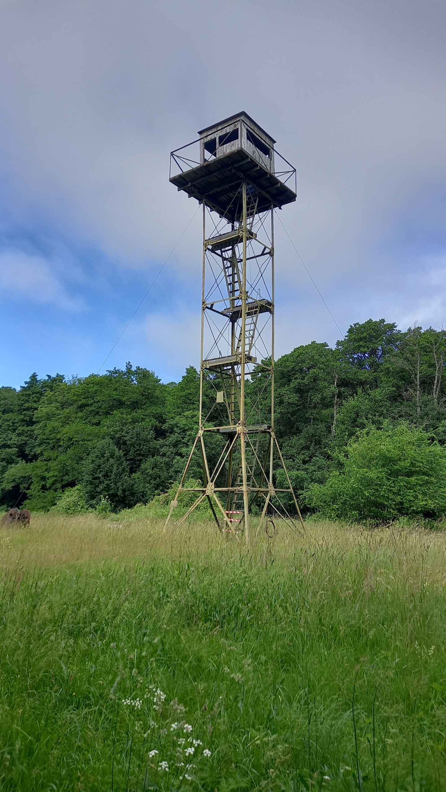
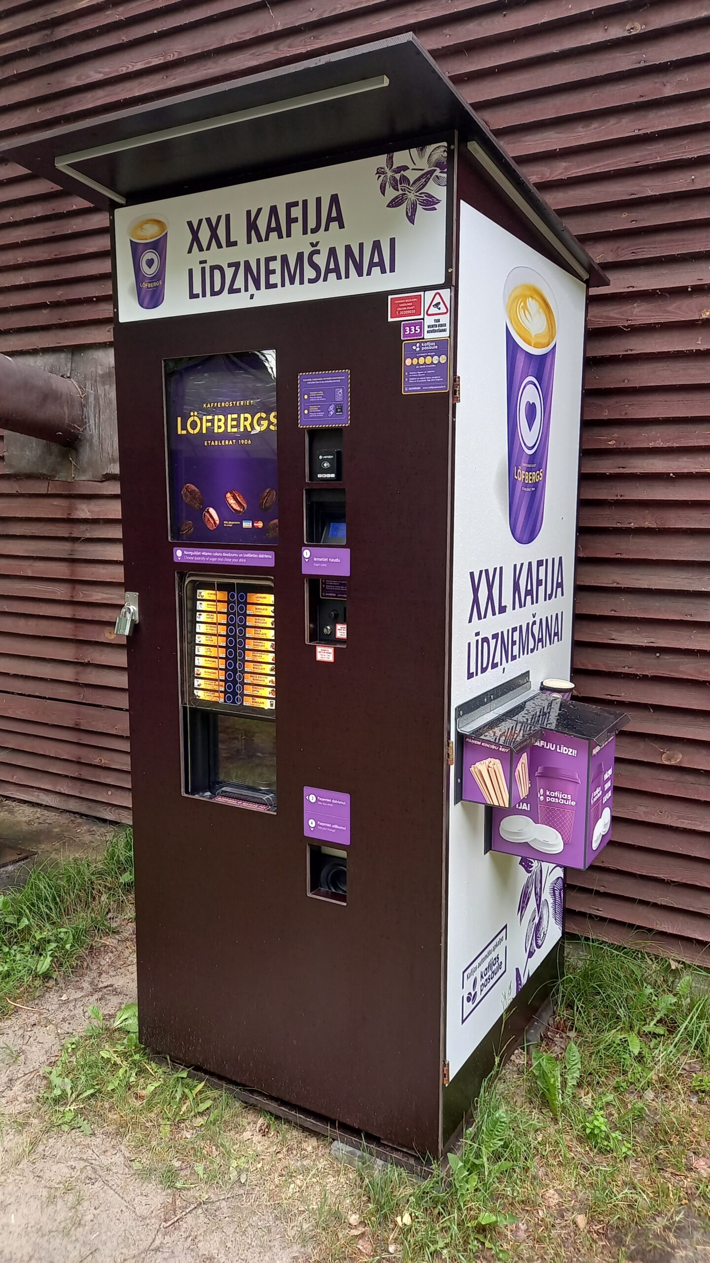
Car park and camper spot at Cape Kolka, in a remote area of seemingly endless pine forests on sandy soil.A lonely stretch of coastline on Cape Kolka, which was a military restricted zone under Soviet rule.Wetland near Irbene and Cape Kolka.The gaze that once controlled: a Soviet border watchtower, photographed here in Estonia, of the identical design once found along the Courland coast too – lookout posts of the border troops, from which the entire Baltic coastline was kept under seamless observation. For the local population this meant: their own beach was a restricted zone. Access only with a pass, only at designated points, and only during daylight; fishing boats were strictly regulated, every movement towards the sea was watched – out of fear of escape attempts across the Baltic Sea to the West. An entire generation grew up on a coast that was geographically their home, yet in practice kept them locked out of their own country.From restricted zone to showcase vending machine: where until 1994 watchtowers and barbed wire denied any free access to the coast, today a coffee vending machine of the Swedish traditional brand Löfbergs Lila stands in the middle of the forest near Irbene – for Swedes, what Jacobs or Tchibo is for Germans: the everyday brand on the coffee shelf, founded in 1906. That this particular piece of everyday Swedish culture should turn up here, in what was once a hermetically sealed border zone, symbolically shows where Latvia has oriented itself since joining the EU and NATO in 2004: towards Scandinavia rather than towards Russia. But the real punchline is a different one: the machine, with its card payment and video surveillance, is technically more advanced than one often finds at comparable locations in Sweden itself – Latvia has long since overtaken its great role model when it comes to everyday digitalisation.
DATENSCHUTZEINSTELLUNGEN - Diese Webseite verwendet Cookies. Wir verwenden Cookies, um Inhalte und Anzeigen zu personalisieren, Funktionen für soziale Medien anbieten zu können und die Zugriffe auf unsere Website zu analysieren. Sie geben Einwilligung zu unseren Cookies, wenn Sie unsere Webseite weiterhin nutzen. Für den Betrieb der Website nicht notwendige Cookies können Sie hier in den Einstellungen deaktivieren:
This website uses cookies to improve your experience while you navigate through the website. Out of these, the cookies that are categorized as necessary are stored on your browser as they are essential for the working of basic functionalities of the website. We also use third-party cookies that help us analyze and understand how you use this website. These cookies will be stored in your browser only with your consent. You also have the option to opt-out of these cookies. But opting out of some of these cookies may affect your browsing experience.
Necessary cookies are absolutely essential for the website to function properly. These cookies ensure basic functionalities and security features of the website, anonymously.
Cookie
Dauer
Beschreibung
cookielawinfo-checkbox-analytics
11 months
This cookie is set by GDPR Cookie Consent plugin. The cookie is used to store the user consent for the cookies in the category "Analytics".
cookielawinfo-checkbox-functional
11 months
The cookie is set by GDPR cookie consent to record the user consent for the cookies in the category "Functional".
cookielawinfo-checkbox-necessary
11 months
This cookie is set by GDPR Cookie Consent plugin. The cookies is used to store the user consent for the cookies in the category "Necessary".
cookielawinfo-checkbox-others
11 months
This cookie is set by GDPR Cookie Consent plugin. The cookie is used to store the user consent for the cookies in the category "Other.
cookielawinfo-checkbox-performance
11 months
This cookie is set by GDPR Cookie Consent plugin. The cookie is used to store the user consent for the cookies in the category "Performance".
viewed_cookie_policy
11 months
The cookie is set by the GDPR Cookie Consent plugin and is used to store whether or not user has consented to the use of cookies. It does not store any personal data.
Functional cookies help to perform certain functionalities like sharing the content of the website on social media platforms, collect feedbacks, and other third-party features.
Performance cookies are used to understand and analyze the key performance indexes of the website which helps in delivering a better user experience for the visitors.
Analytical cookies are used to understand how visitors interact with the website. These cookies help provide information on metrics the number of visitors, bounce rate, traffic source, etc.
Advertisement cookies are used to provide visitors with relevant ads and marketing campaigns. These cookies track visitors across websites and collect information to provide customized ads.